
Shown is a 2 stage BFO for use with the ugly 40 meter superhets with a 4.00 MHz IF. This is a design by W7ZOI which I have used from 3.5 to 9 MHz by only changing the crystal and the Q2 output coil and capacitor values to suit the frequency of choice.
The output coil is 59 primary and 12 secondary windings on a T68-2 toroid core.
You will need in the order of 79 pF to resonate this coil, thus a 68 pF plus a 5-20 pF variable works well. If you do not have a T68-2 core, a T50-2 could be used with 30 AWG wire which is a bit difficult so you could opt for an XL of 200 ohms which would be 40 primary and 8 secondary turns on a T50-2 core. You would need ~200 pF to resonate such a coil and the BFO would have reduced output power, but would still work okay. If you design your own tank, you probably should not use an XL/XC less than 190 ohms for the output stage at 4 MHz. Use a 5:1 turns ratio for primary to secondary windings.
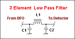
It wouldn't hurt to follow the Popcorn Superhet BFO with a low pass filter.
A simple pi-type 3 element filter is suitable. Since I had a couple of 470 pF caps left over, I made a low pass filter using a 6.8 MHz cutoff frequency with a 1.17 uH inductor.
A 1.17 uH inductor using a T37-2 core requires 17 turns while on a T50-2 core requires 15 turns. Caps were inexpensive monolithic ceramics from DigiKey. The filter is shown below,
L1 = 1.17uH , C1 and C2 = 470 pF. If you want, you may use other cutoff frequencies to suit any junkbox caps you have on hand and use an XL/XC of 50 ohms.

Construction
Keep component leads as short as possible to promote stability. Do not omit the zener
diode D1. I thought of using a small ferrite bead on the base of Q2 and will try it on the next version of this BFO that I make. The BFO, if unstable can break into all sorts of weird
AF sound effects that are very annoying. The BFO should ideally be in a shielded box, but
many amateurs have good results by just placing the BFO strategically in the receiver chassis. When winding L1, make sure you wind the secondary coil so that the secondary's grounded end is on the cold side of the primary coil that connects to the 100 ohm resistor and positive voltage.
I just pick one end of the primary coil and close wind the secondary coil from this point in the same direction for the correct number of windings. Then the starting point of the secondary can be grounded and the other end connected to the detector or a low pass filter.
After building the coil, temporarily place a 51 ohm resistor from the secondary output
lead to ground. Then you can test and peak the tuning of the output tank into a load.
Leave the resistor in place for all your testing work such as crystal matching or RF stage testing until you are ready to connect it to the product detector. The 60 pF variable cap connected between the crystal and ground is used to set the beat frequency of the BFO.
Adjust it to get a good sounding beat note when listening to a station. You will notice
that the beat frequency can be tuned roughly by just listening to 40 meter band noise in the headphones and then tweaked on an active QSO.
Home