 Tube
Radio Australia
Tube
Radio Australia 
AWA BTM-2M AM
Transmitter Rescue
|
This is the Story of the
Recovery of the AWA BTM-2M AM Broadcast Transmitter from the 4CC transmitter
site in Biloela. Thanks to the efforts of Keith Evans and Brandon Gordon VK4VIP for allowing
us to save the transmitter and arranging a time for collection. Also thanks to Ray Robinson for keeping me awake on
the trip up and assisting with the heavy lifting. History: This
Transmitter was installed into 4GY originally as a brand new transmitter in
late 60's and it was set to 1350 KHz at the old transmitter site at Monkland
Queensland, it was then moved to Wolvi, Queensland in 1975 as TX No-2 with a
new main TX being a RCA 5 kW Ampliphase. It was set
to a new frequency of 560 KHz and to 558 KHz in 1978. It was
de-commissioned in 1986 when a new MW10B went into the site as the new main
transmitter for AM Stereo and the RCA TX became TX- No 2 as a Backup TX. GY was owned
by Wesgo at this point as was 4CC, so the AWA transmitter was moved to
Biloela in the late 80's and upgraded in the early 2000’s. The AWA
transmitter was operated as the Backup until parts became an issue whereby it
was decommissioned until its removal by the Tube Radio Australia Team, Ray
Poularas and Ray Robinson. . Specifications: Model: AWA
BTM-2M Serial
Number: 43 Frequency:
666khz Power:
2.5kw (2500w) Power
Requirement: 3 Phase 415v & Single Phase 240v Filament Hours:
0648564 (taken by front metre) Dimensions:
Height- 2.23m, Width- 0.98m, Depth- 0.93m Weight:
1750 pounds (as per the manual) 800+ Killos This is a piece of History for 4CC Biloela and as of the
18-04-2016 has gone to a new home in Sydney. The old original AWA Tube AM transmitter that
provided listeners with music and programs on 666 kHz from Biloela for many
years in the 80s, 90s, and has now finally been removed, after it was
replaced with a new state of the art, fully Solid State AM Transmitter. The AWA BTM-2M
transmitter built 1966, It ran on 3 phase 415 V
power and drew 20 Amps per phase at full output and 100% modulation. The control circuit, minor HT, air
blower and filaments operate on single phase. The 5,500 V a.c. three phase transformer cannot operate on single phase. It can be run
again as before but only when the 3 phase contactor for the High Tension
closes onto the 3 phase power. It’s now gone to Sydney to be placed in a museum and
will be converted to the 160 metre amateur radio
band on approx. 1843kHz AM. And run at legal limits for Amateur operations. |
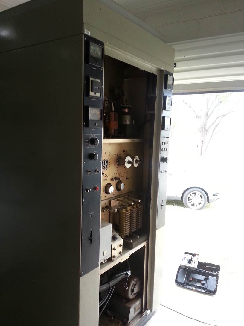
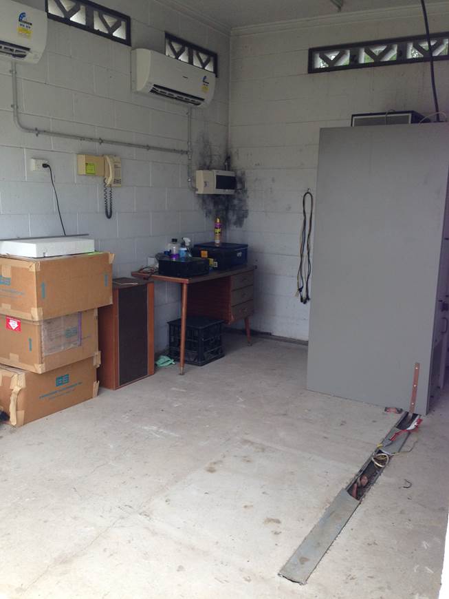
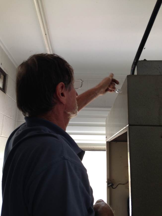
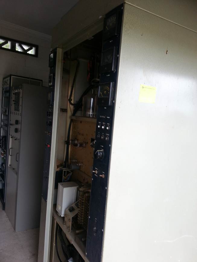
The Transmitter in its original position…
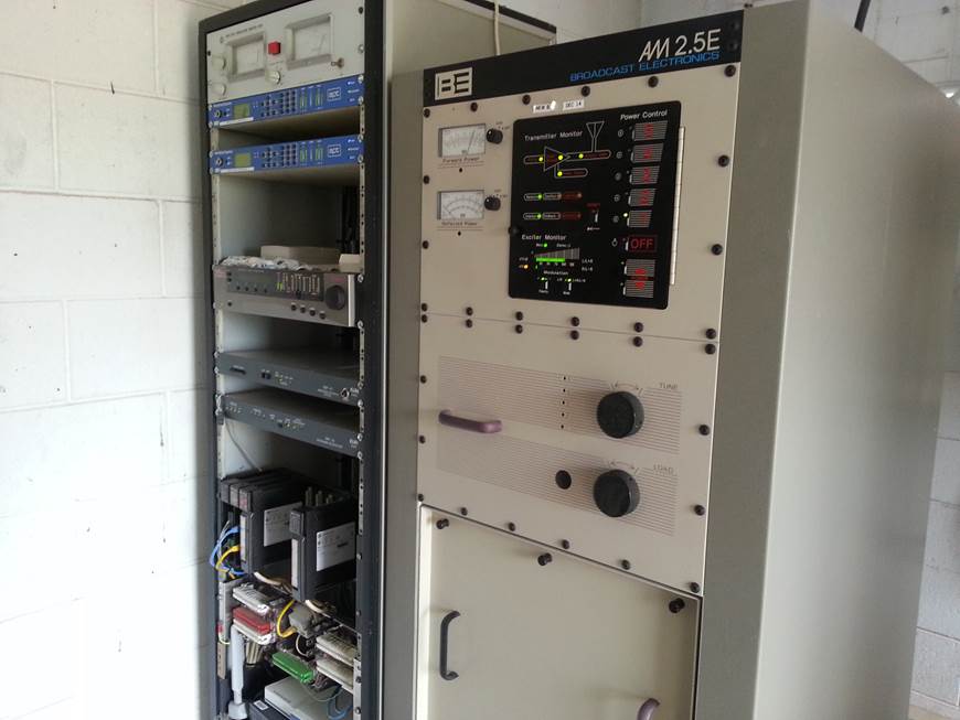
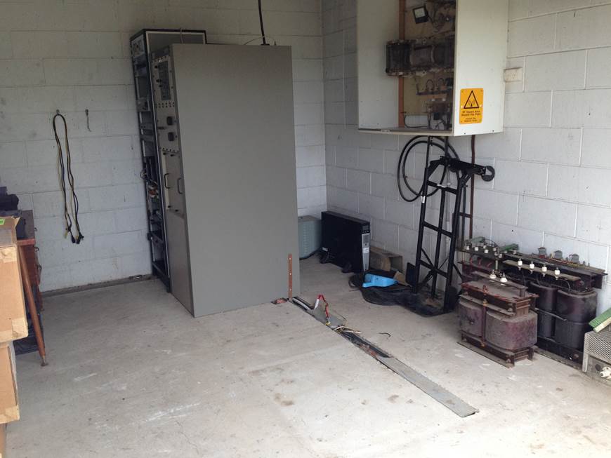
The new transmitter solid state, only two
racks of kit
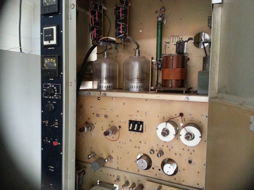
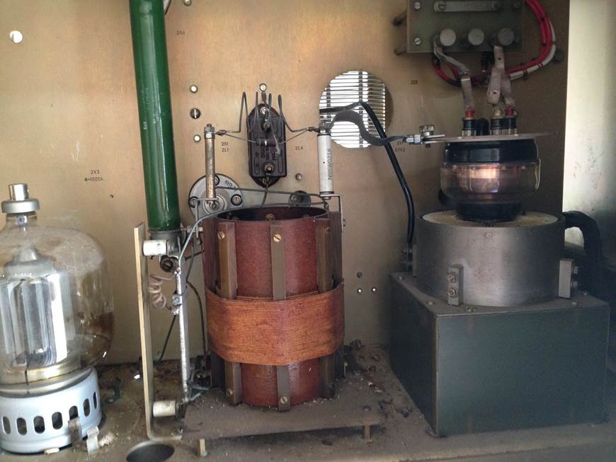
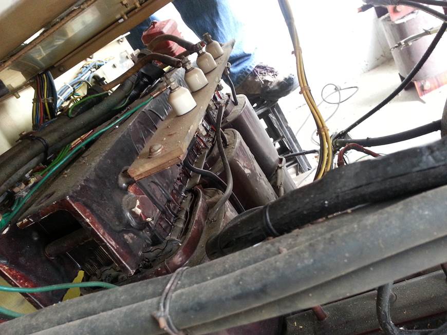
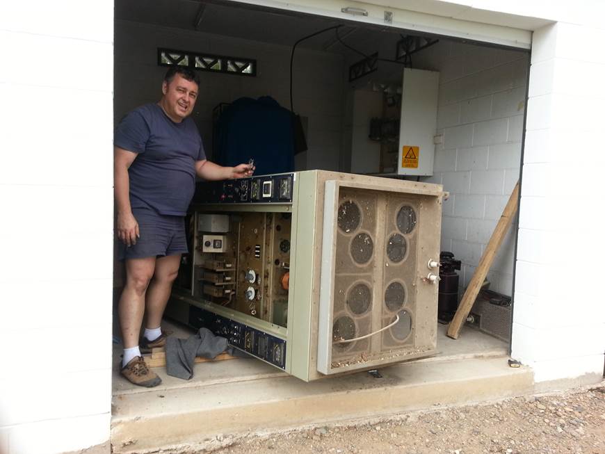
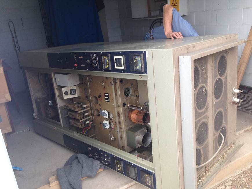
The Two Modulator tubes and the RF PA. Driver
section for the Modulator and crystals
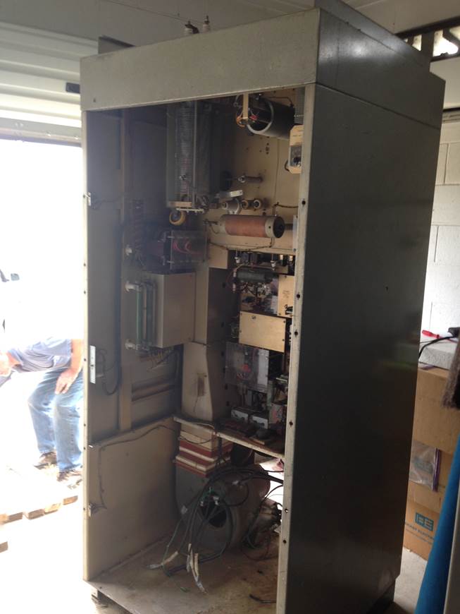
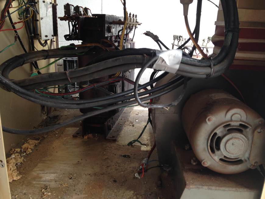
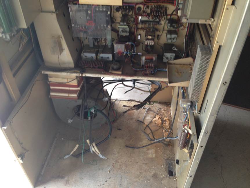
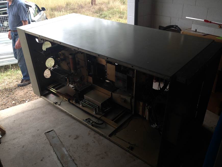
Rear View with the Power Transformers remove.
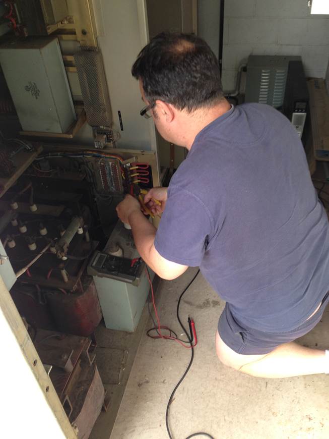
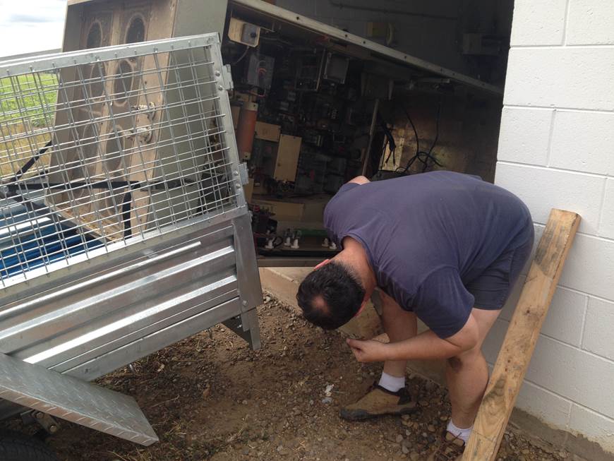
Dissconnecting the 240v and 415v mains, note
check three times and then ground test everything before unscrewing the
terminals…!
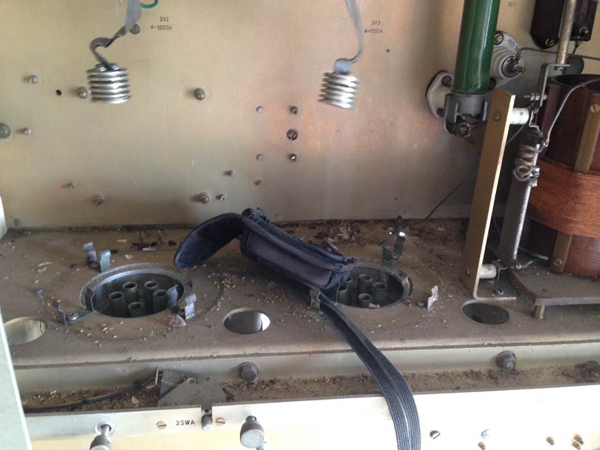
The Modulator sockets
PA tube and Blower output
The 4cx 1000’s
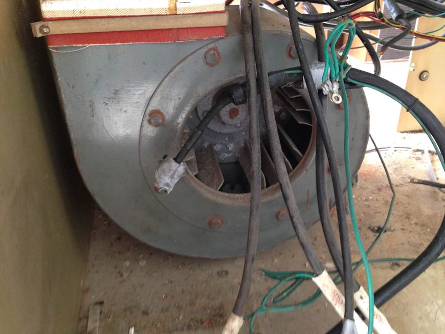
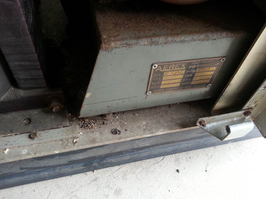
The blower unit
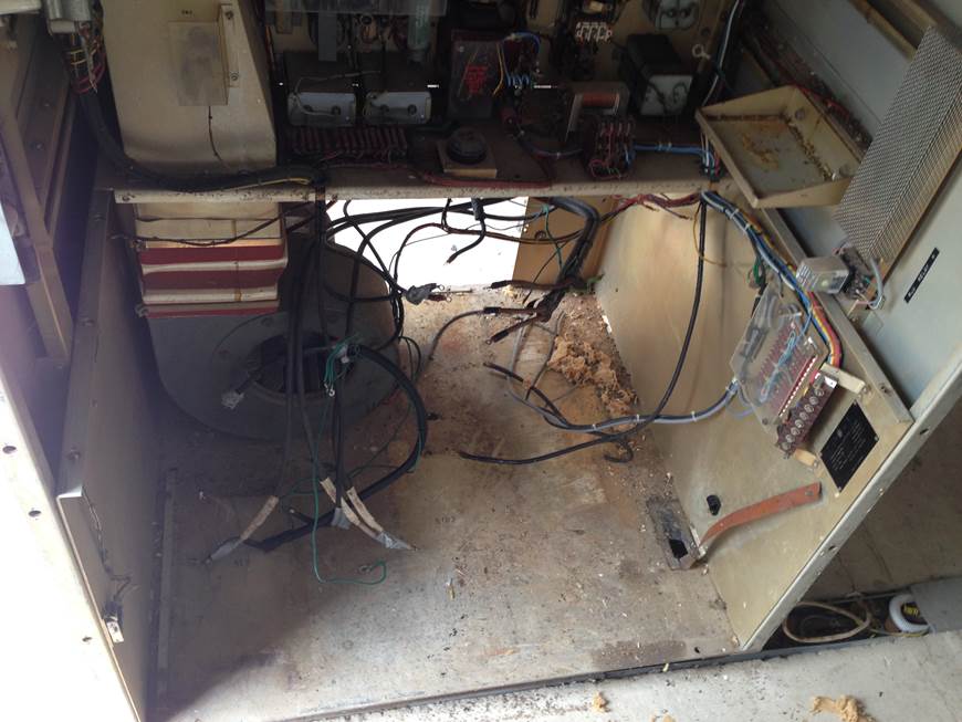
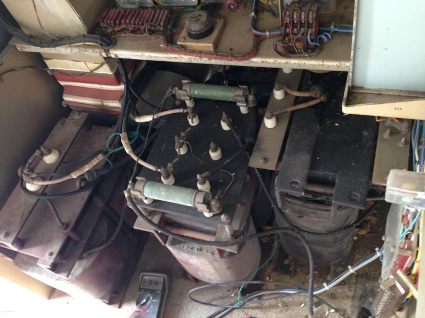
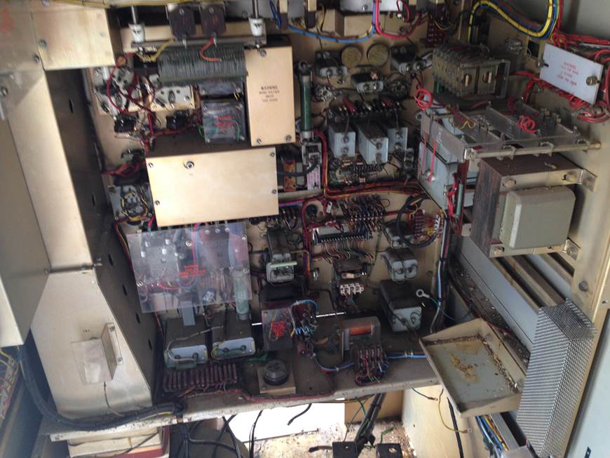
Bottom ot the TX……
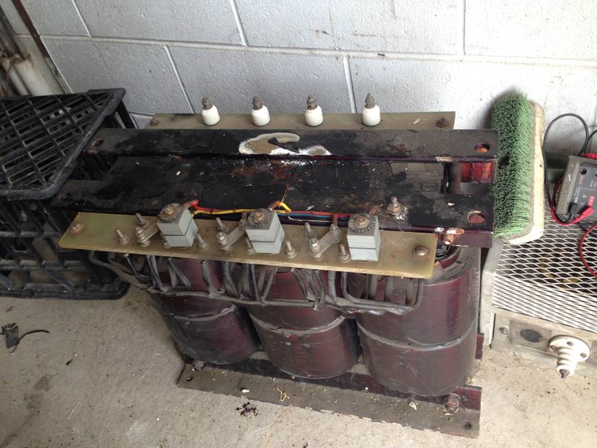
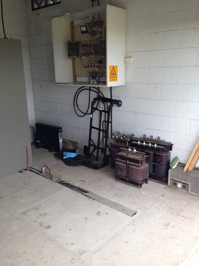
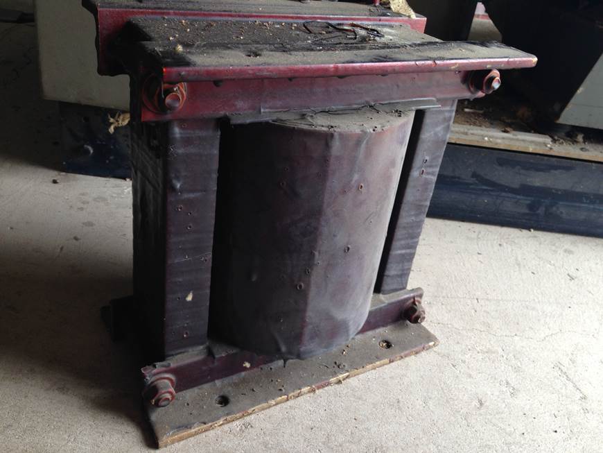
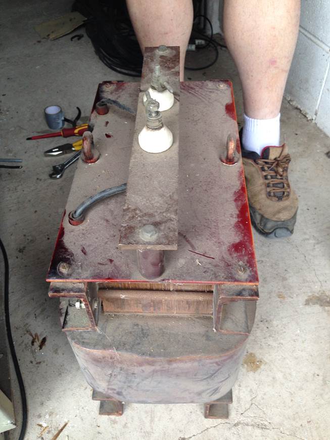
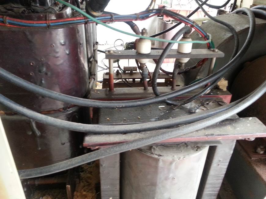
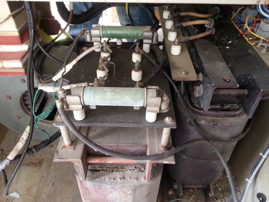
The three phase transformer …. Very Heavy.
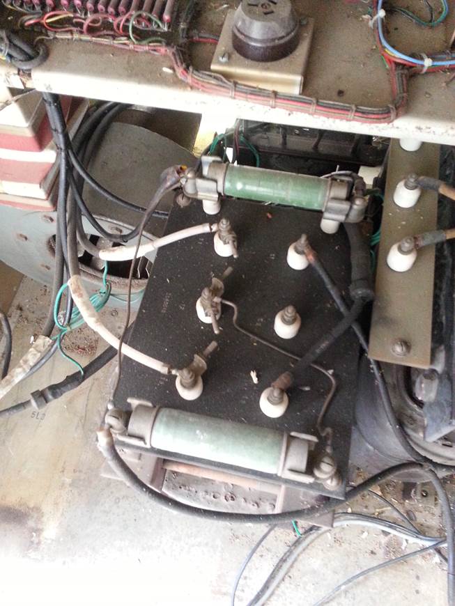
The LV Power Choke with two smaller
transformers and the Capacitors
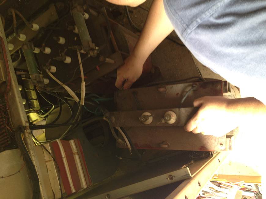
Sliding out the three phase transformer..
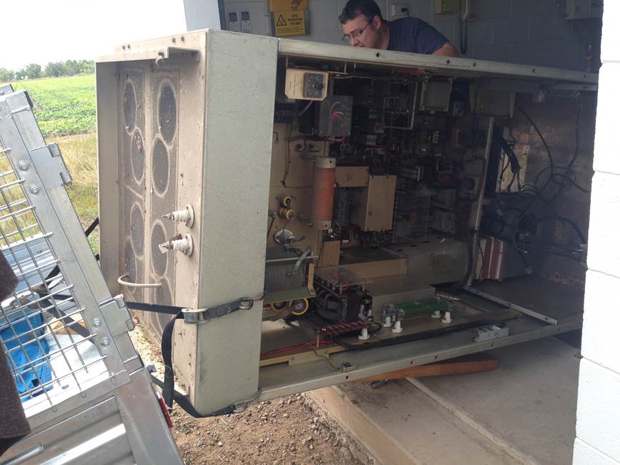
The rear of the TX…
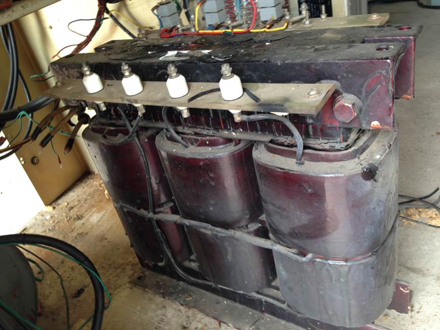
Close up of the three phase transformer.
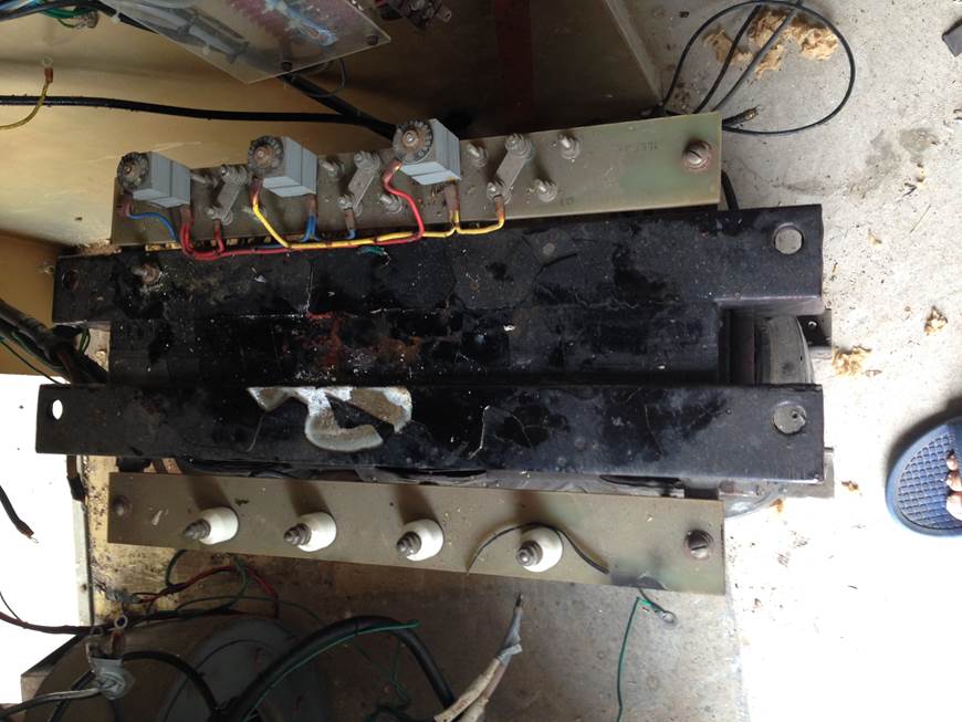
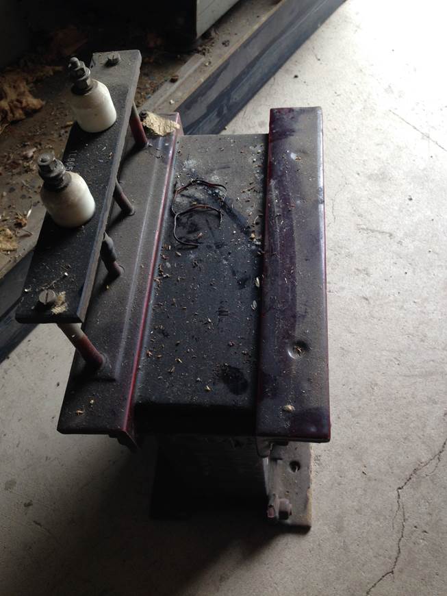
Low Voltage side of the main transformer.
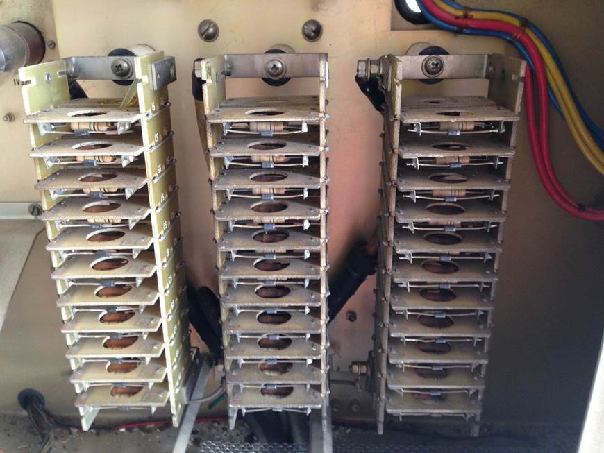
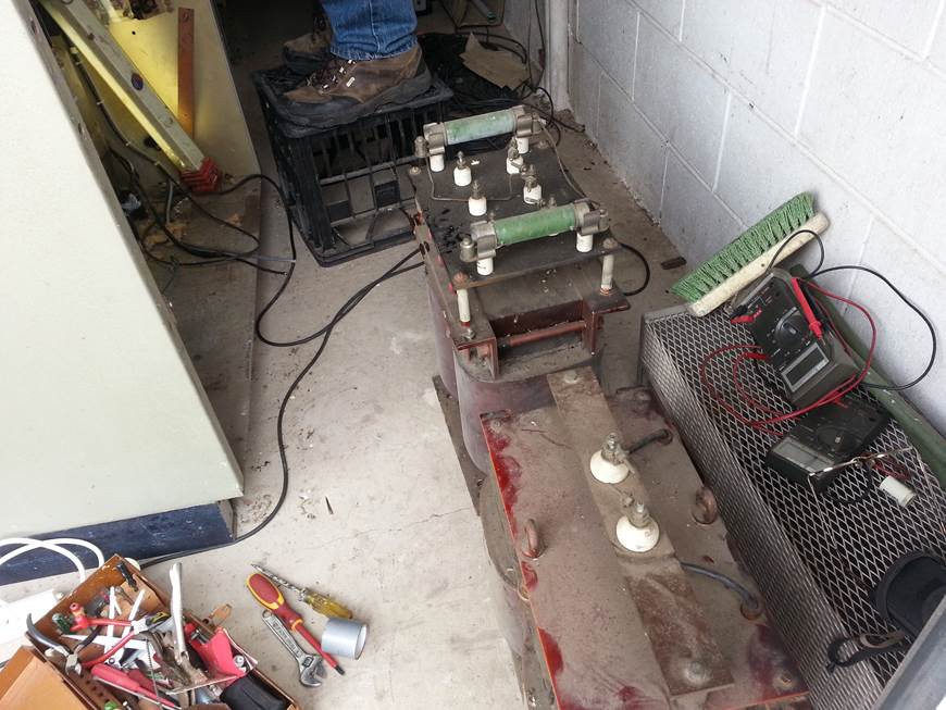
Voltage rectifiers
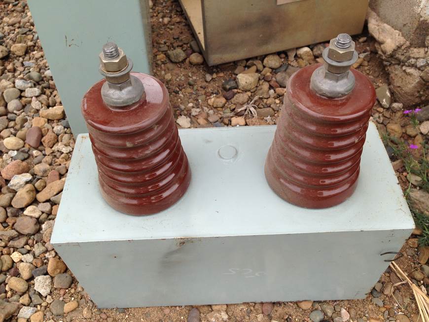
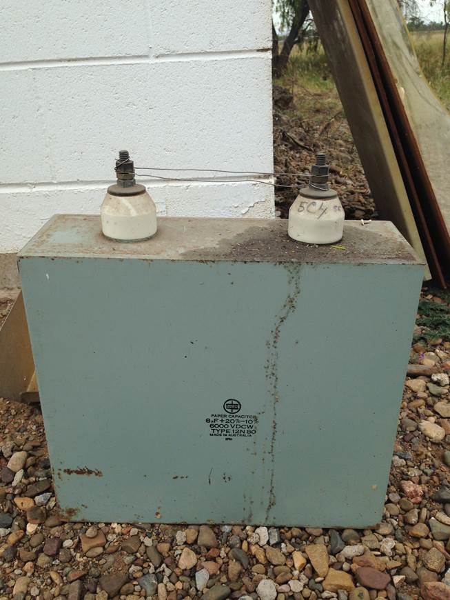
Oil Filled Capacitor No 1 the Big one….
HV Choke transformer 5000V
Choke HV 5000V
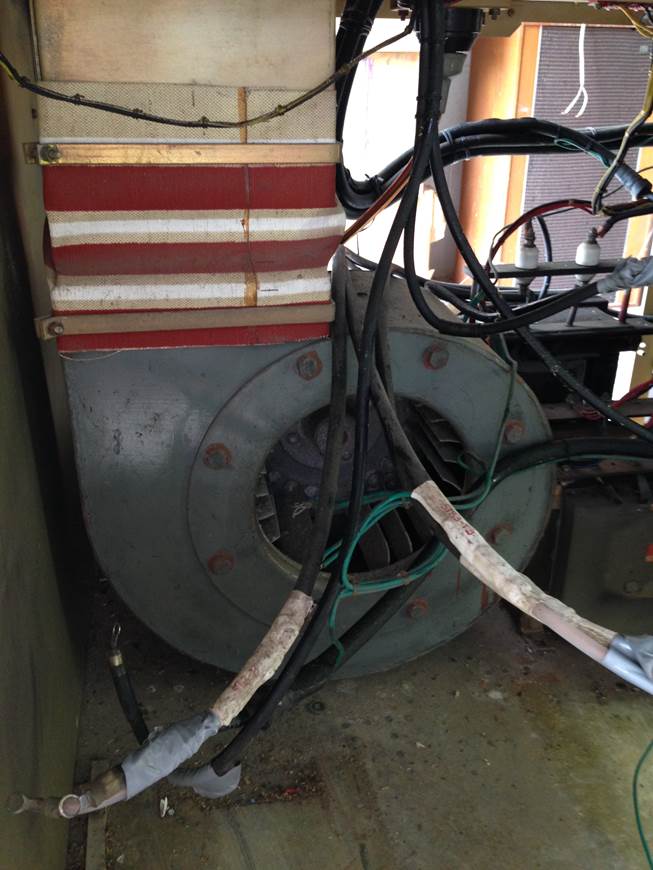
Blower Unit for the output tube, to prevent the
tiube from overheating with continuos use
Low Voltage transformer 350v and 250v
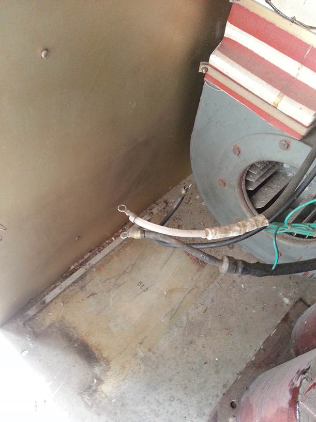
Disconnecting the RF cable, the transmitter
that was running next to this transmitter had to have the power reduced so that
the risk of cross RF was reduced. Even without a direct connection the RF can
be induced into the Tank coils from the active transmitter and give you a nasty
RF burn or worse.
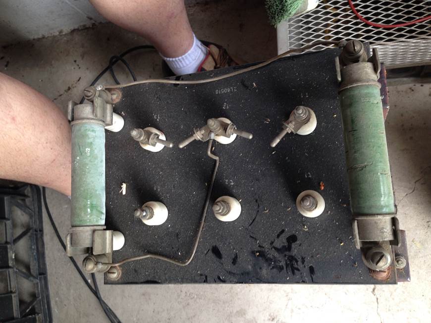
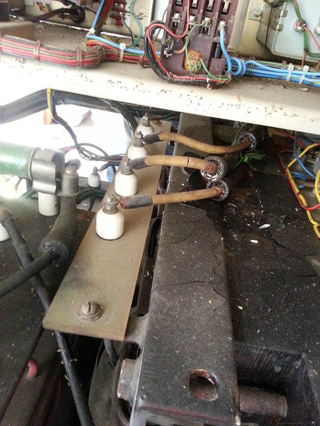
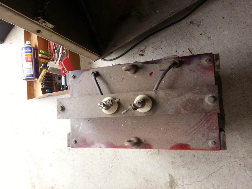
LV
choke Transformer Note the Ceramic terminals. This needs to conduct
massive current so its Heavy.
Disconnecting the Earths
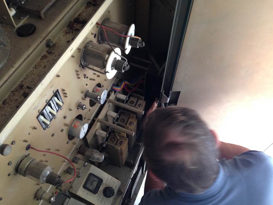
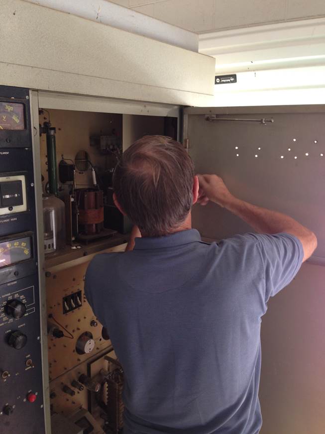
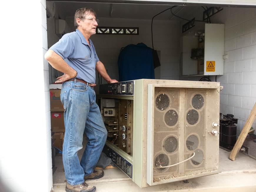
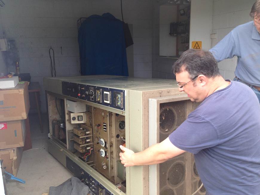
Nice shot looking down the front panel, note the two 6146 driver tubes for the 4CX100 Modulator tubes and the test meter built into the cabinet. Ray Robinson working on the front door hinge. Notice the Test meter, according to the diagram it has RF and 5000V across it, so its mounted inside the cabinet.
Small Cap is Out
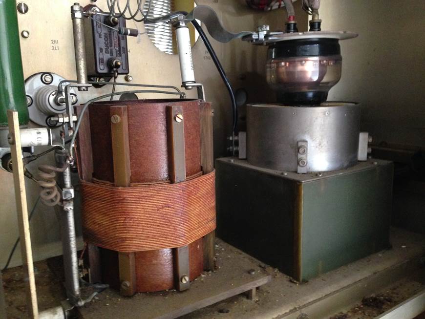
Driver Tank to the PA output tube….
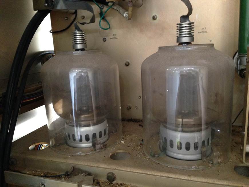
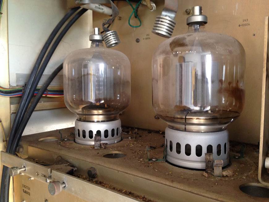
Glass covers on the Modulator tubes Very
Dusty and Dirty inside
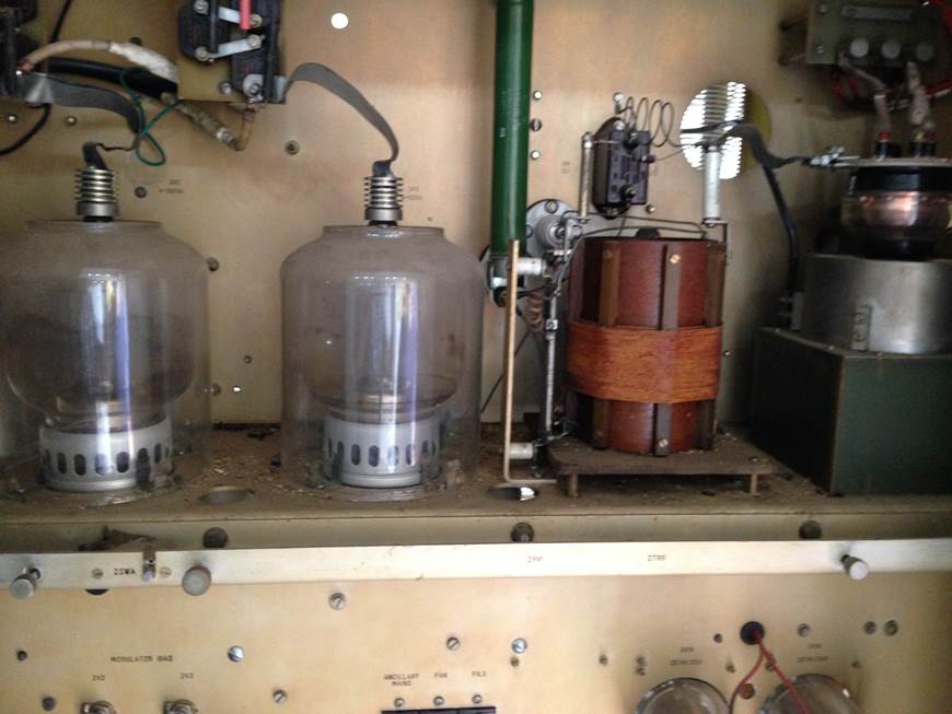
Modulator Deck shots
I know that door will come off, its just
rusted on
The door is finaly off….
Making the first Cut on the Mains after
isolation of the TX..
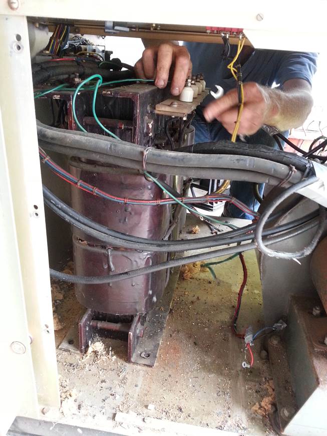
Dissconnection of the three phase transformer
Three Phase connections
Blower unit needs attention
Choke Connections
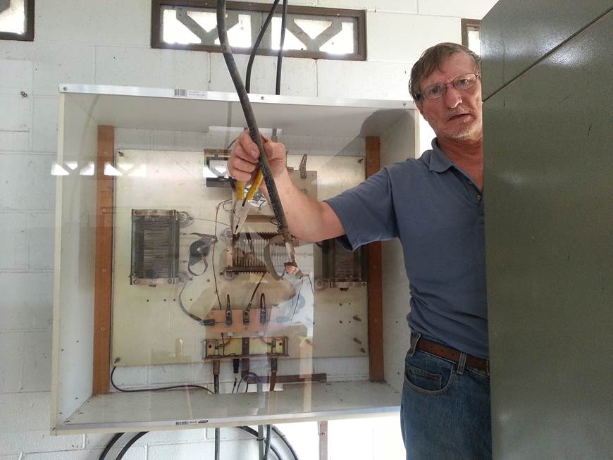
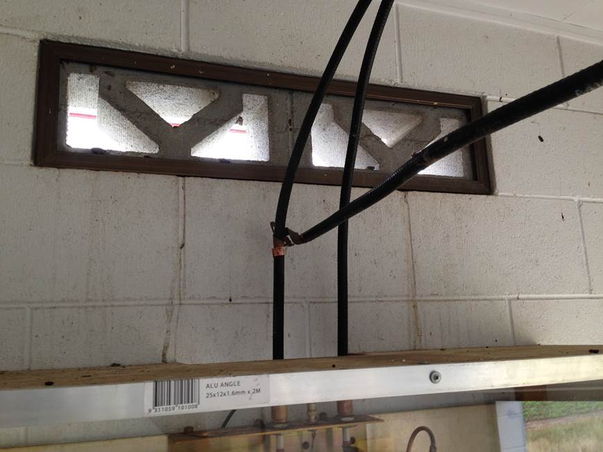
Nice shot of the Antenna inputs from both
Masts into the switching and loading coils, with Ray holding the removed output
cable.. No RF burns and its all safe.
Special safety boots and standing on the RF insulating stand….!

Making the RF antenna Cut….
LV transformer connections
HV three phase connections
LV connections
Its Out..
Choke..
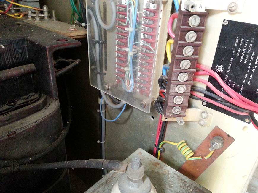
Closeup of the 425v and 240v connections
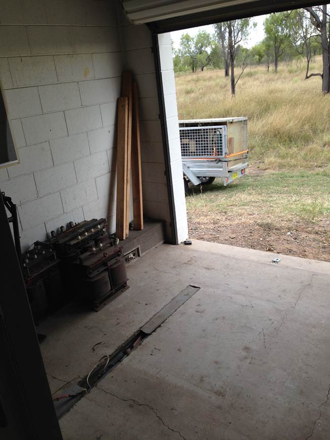
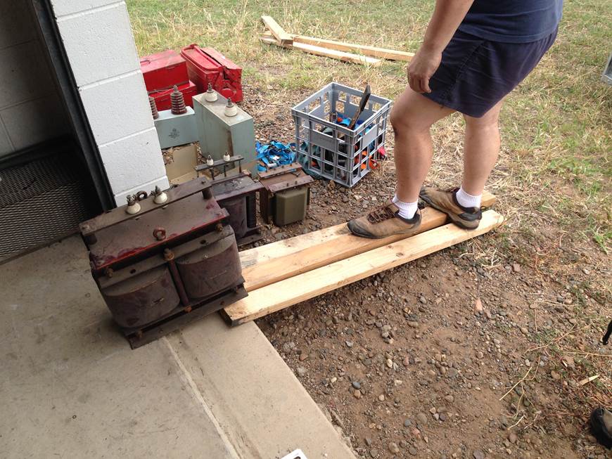
The transformers are out
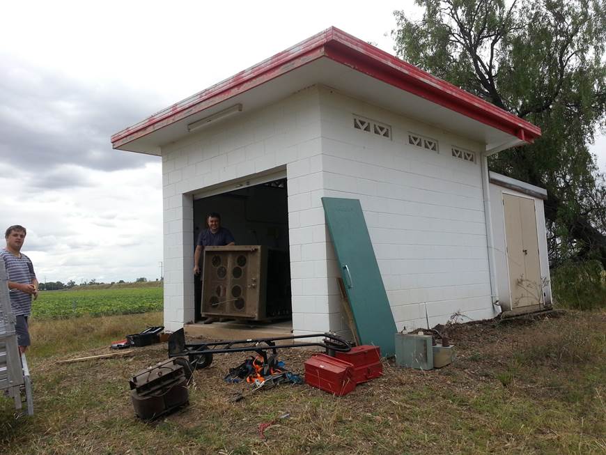
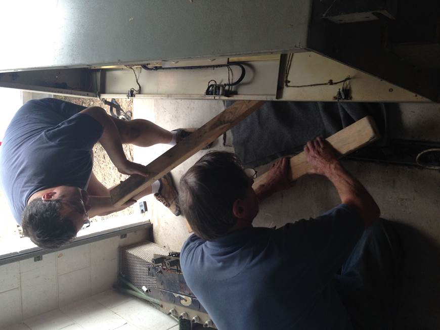
Getting it out the door from the transmitter
shed, Note the transmitter was too big to come out standing up, which leads me
to believe the shed was build around it….
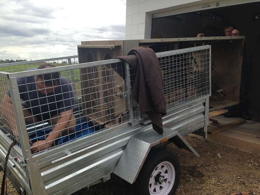
Yep now how to get this 350KG transmitter
case onto the trailer??
The look of contemplation, how are we going to lift this?
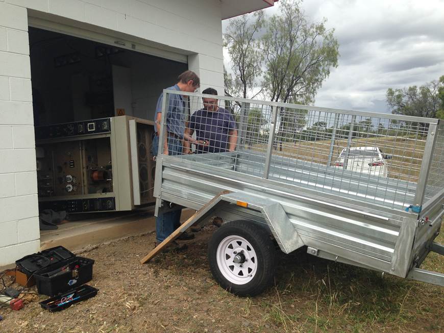
Hmmm…. It’s very heavy…!
Yep too heavy to move into the trailer by
hand..
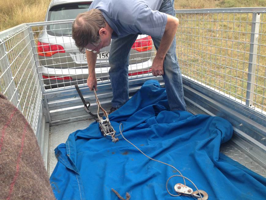
Special tools needed a Hand winch
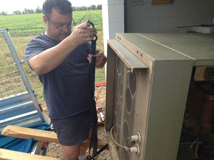
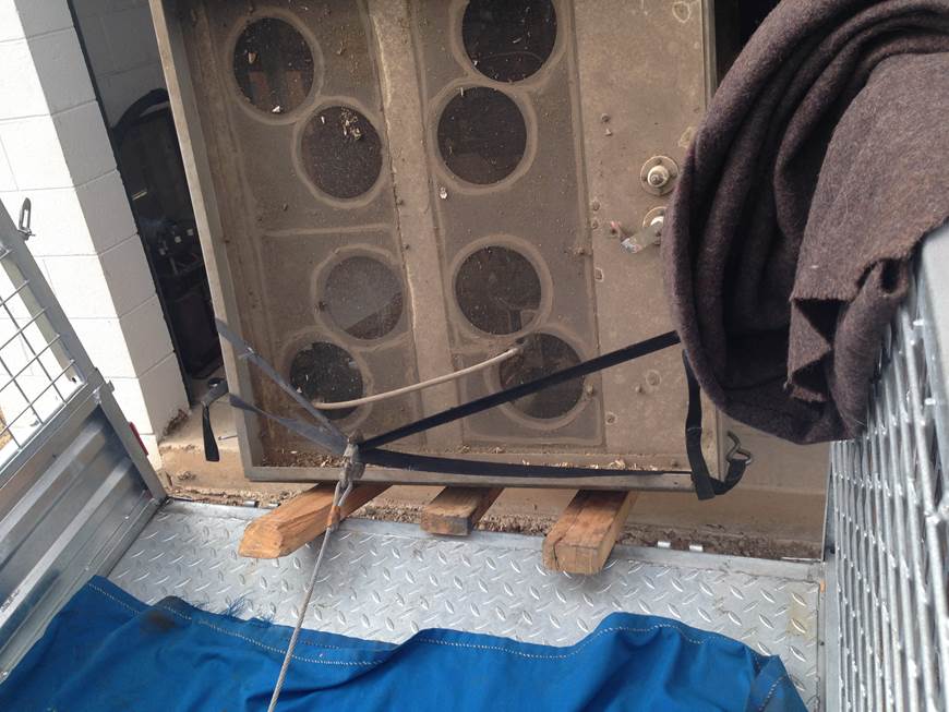
Strapping it up
Timber skids reminiscent of building the Pyramids
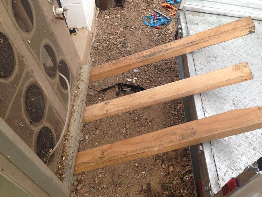
Ramp made
Ready to go….!
Pull it up….!
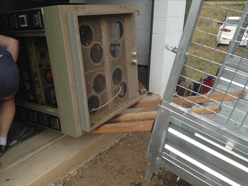
On its way up the ramp
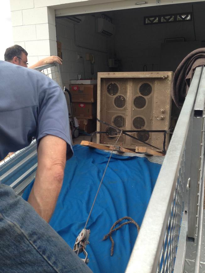
Last lift and its in the trailer….

Some positioning..
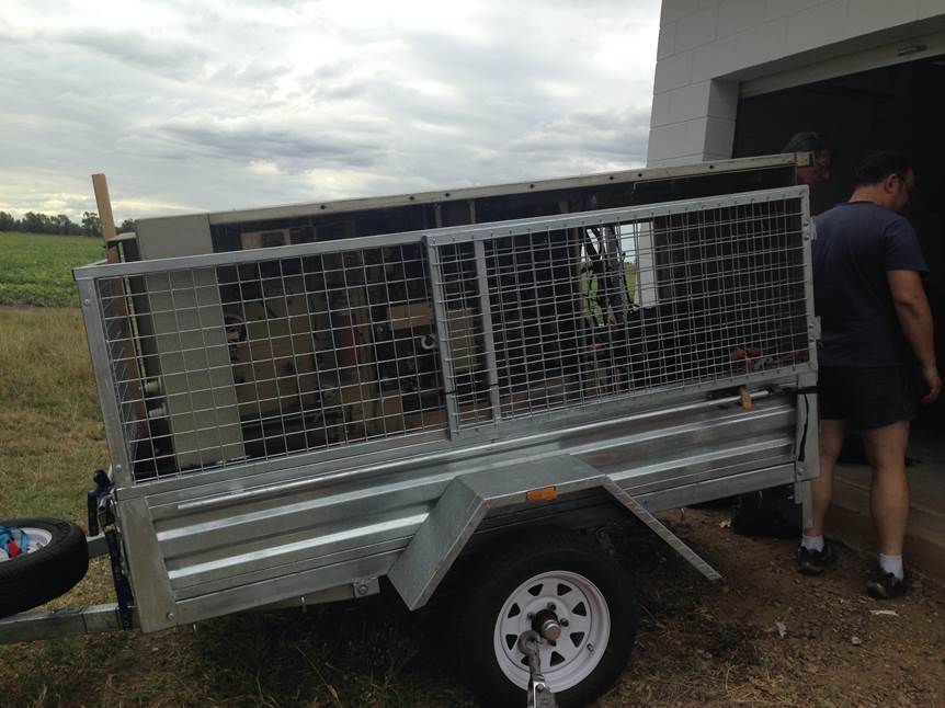
Its IN..!
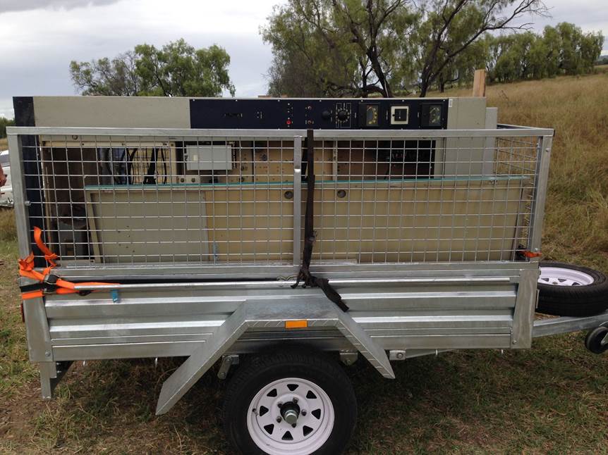
What do you know it Fits….!
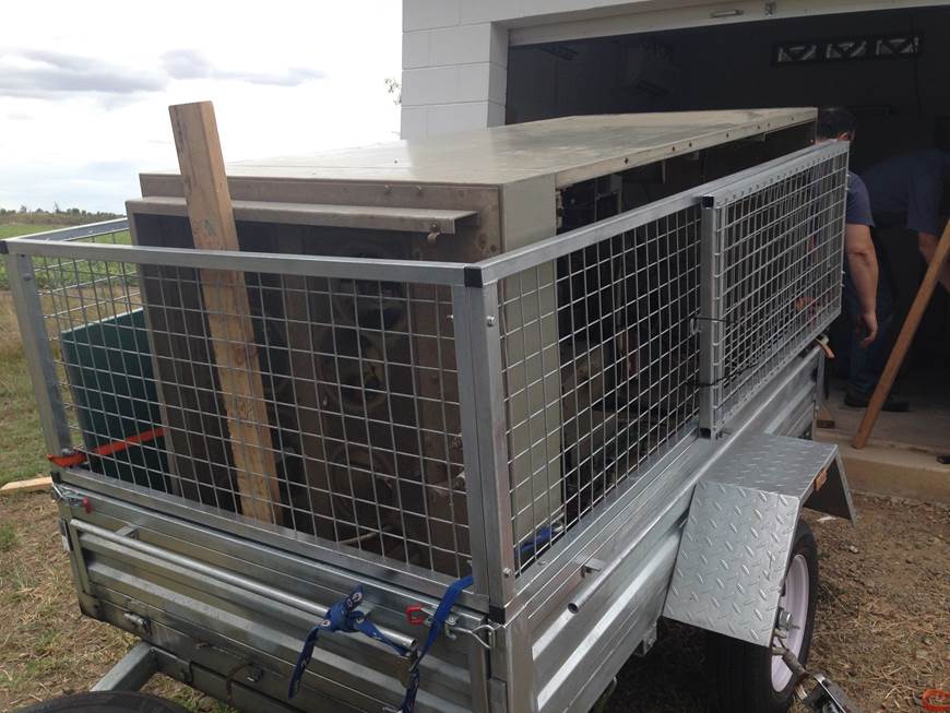
Strapped in for the trip
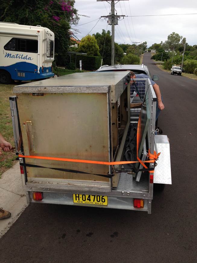
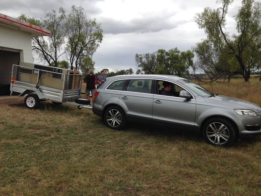
On the road
Spare RF cable
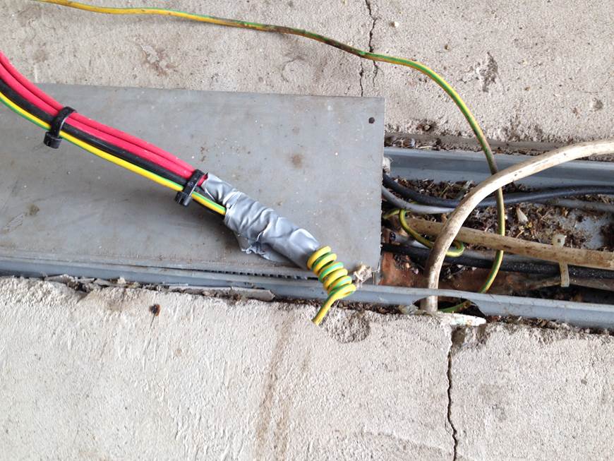
Mains isolated and insulated