 TELEFUNKEN E52 KÖLN Restoration
Here I describe
the restoration of another legendary receiver from the second
world war (WWII), the Telefunken E52 Köln, which was mainly used by the
German Luftwaffe for ground stations and vehicles.
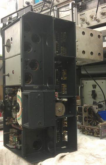
The receiver was far ahead of competing designs of that time both in
construction and performance. The chassis was molded in an aluminum alloy which
gave good stability and heat dissipation, and the receiver was built in
modules, interconnected with a back plane, the valves were interchangeable from
the outside. Sensitivity, selectivity, resolution and stability were
outstanding with 2 RF and 3 IF stages, with continuously variable bandwidth
crystal filters, with a projected photo scale and carefully temperature
compensated circuits.
This E52 was
a Ebay Special, that had
been recovered from a Barn cellar in Russia, it was with a whole load of WWII
German artifacts, that looked like they had been there some 70 years.
All seemed
to be going well it looked like it was original and unmolested with the
original trimmers covers and optional motor tune..
That was until it came time to ship the radio. Despite paying for DHL, my
Russian buddy, found that there was additional paperwork needed to ship this
type of equipment and it was costly. Thinking he was doing the right thing it
went EMS express post. Well two of the
five boxes initially turned up. After waiting another 4 weeks I could see that
the shipment was stuck in the tracking system. E-mails to the EMS Russia office
initially received a response, but as soon as they realized that they had lost
the other three boxes, everything went quite.
After
repeated e-mails and eight months of chasing the seller they finally retuned to
boxes to him. What he didn’t tell me was
that the radio had been damaged while with EMS.
It appeared
that Russian customs had taken the chassis apart by ripping the band change rod
through the switches and the chassis had been dropped breaking one corner. The
small switch finger separators had also been damaged, and when I opened the new
boxes, a found a BAG of smashed parts.
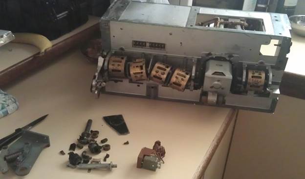
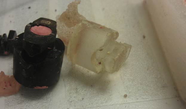
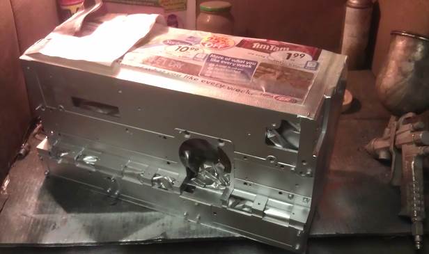
Note the
tuning capacitor and other parts on the bench..! The porcelain shaft was
smashed and many parts were broken. At this point I seriously started to think
about conversion to spares, but as this is a rare radio in this part of the world
and it was an original set.
I decided to
move forward with repair. It was going to be a huge effort having to cast new
switch cams and contact separators so I started with the most difficult parts.
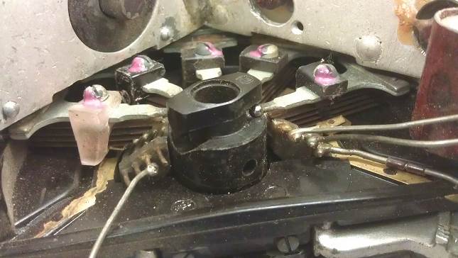
The first part I started with was
the switch CAM This second photo shows its final home and also the home of
one of the switch separators I made.
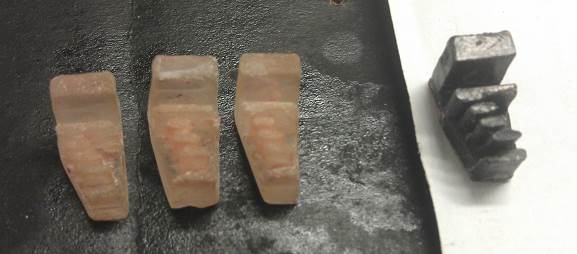
The separators new and the original to
the right, these were made after coating the original in a nonstick wax, and
pushing it into a clay mold, then pouring resin into the mold, the cams were
made in a silicon mold made the same way.
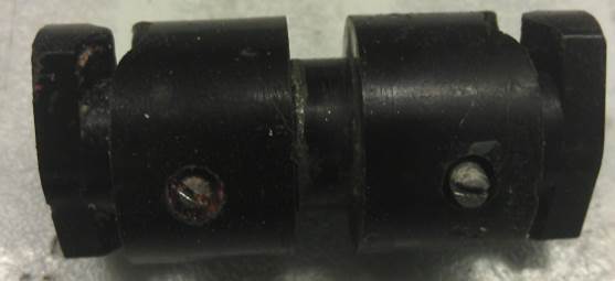
Above shows test fitting of the new Cams with a PEN holding them in
place. Painting the rear of the chassis after
sand blasting, the paint was matched to the rear of the front panel.
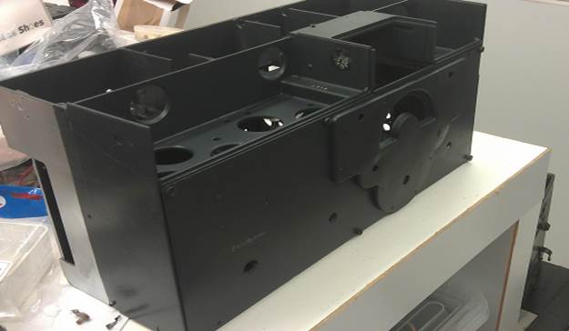
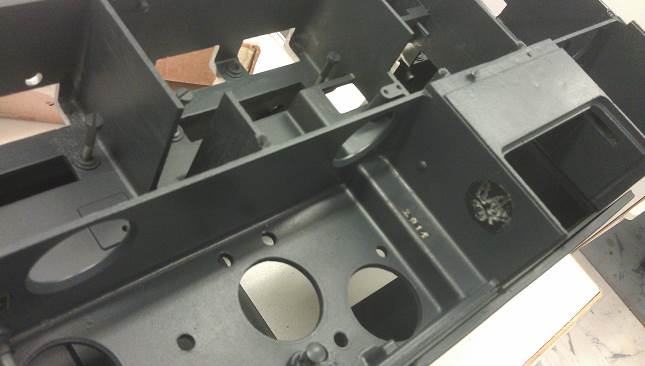
The Chassis after the
repaint, I kept the original serial number and manufacturers stamp

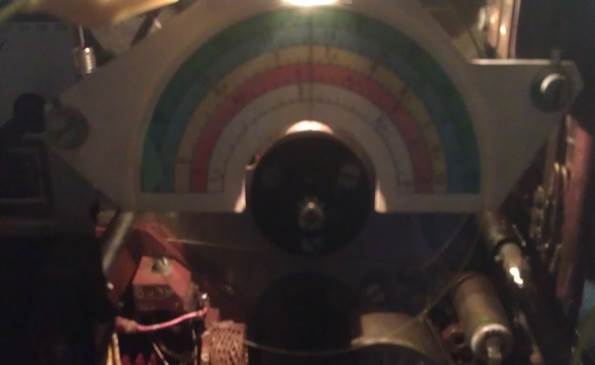
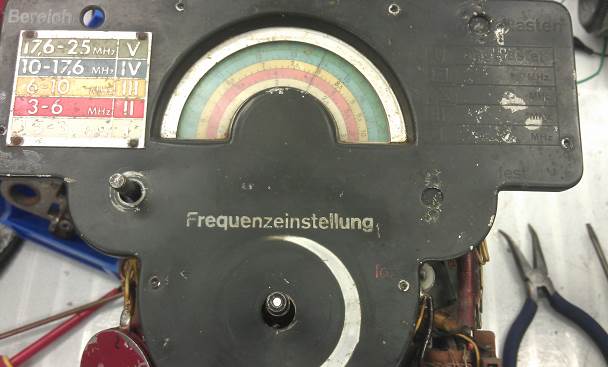
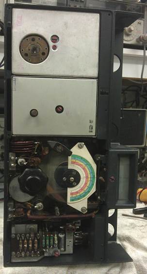
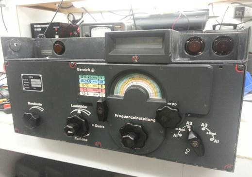
Chassis ready for its parts, Test of the Micro dial, I was
worried that it was worn but on this E52 its white
with black writing
My
Other E52 is Black with White writing, See photo of it at the beginning of this
page.
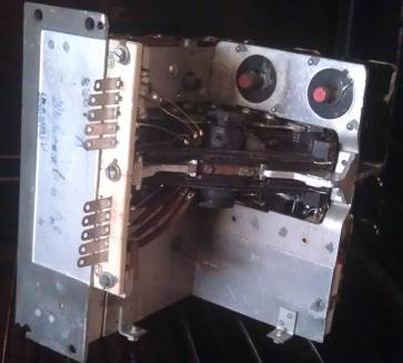
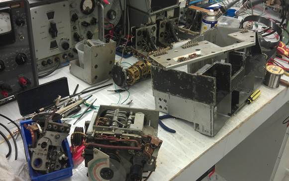
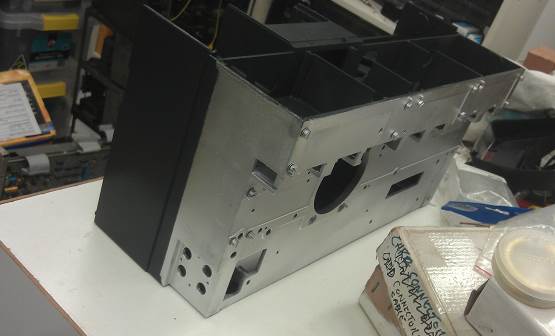
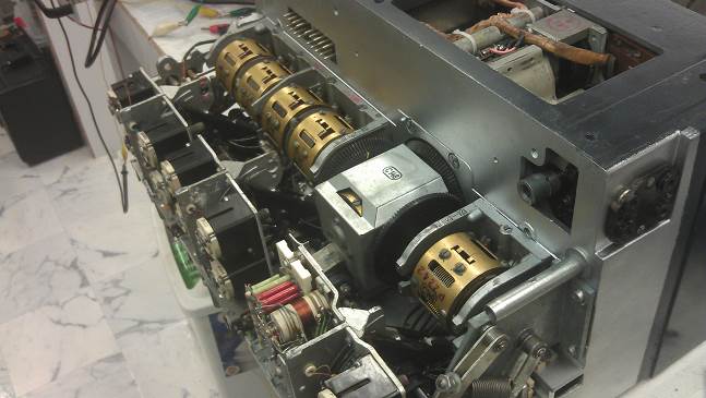
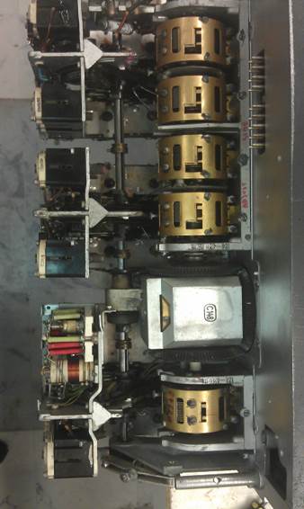
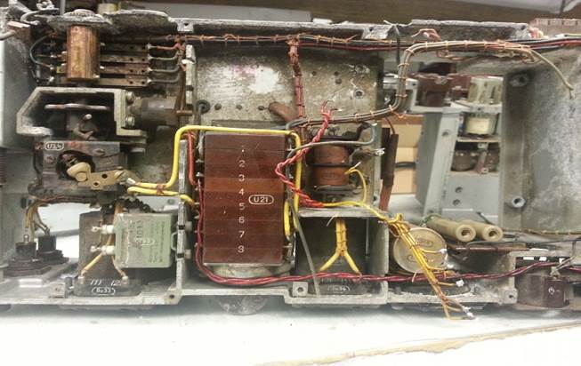
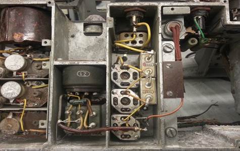
The RF
module after repair of the cams, The auto tune after
repair and cleaning, Rectifier after repair to the Bakelite
The dial after
cleaning
The front before stripping for paint.

Rebuilding the tuning
capacitor. I replace the original shaft with a 9mm Nylon one Capacitor and coils back in the chassis
Switch
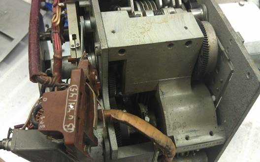
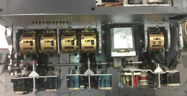
Shaft goes in and all of the spacers for the new cams The RF and Oscillator decks clean and in,
with all original trimmer caps and coils.
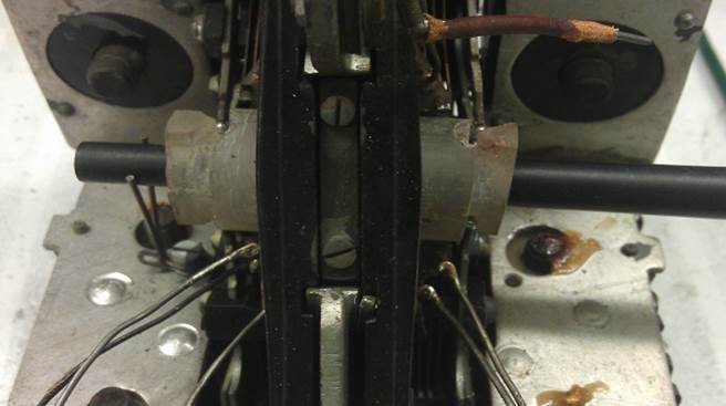
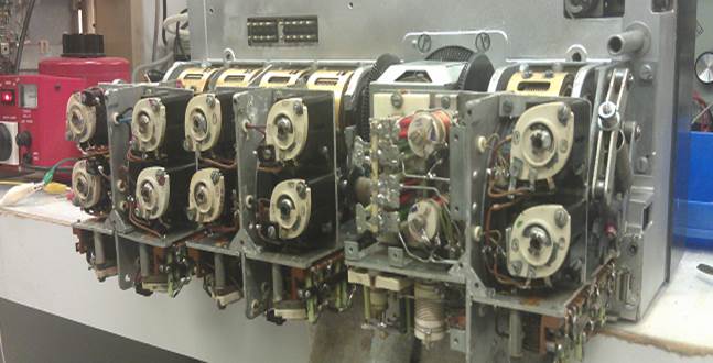
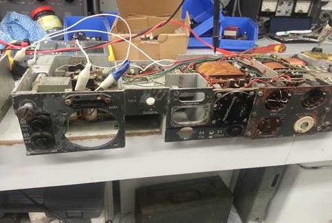
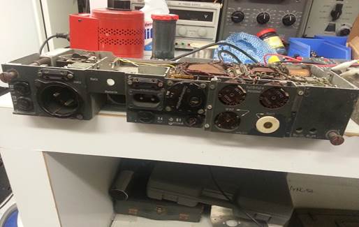
Installing all of the top electronics Shot from the bottom of the set Front modules in and ready.
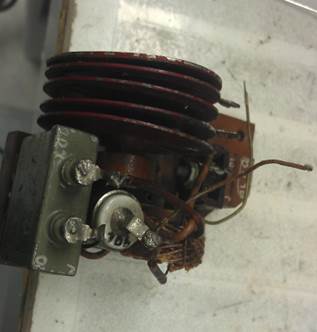
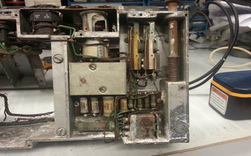
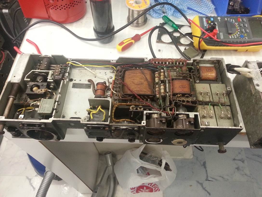
Power Supply Rebuild:
The Original
power supply in this set had a faulty main transformer in the HV winding,
caused by a shorted choke.
I managed to
get a few basket cases from the internet and a mate and set out to rebuild two
working power supplies.
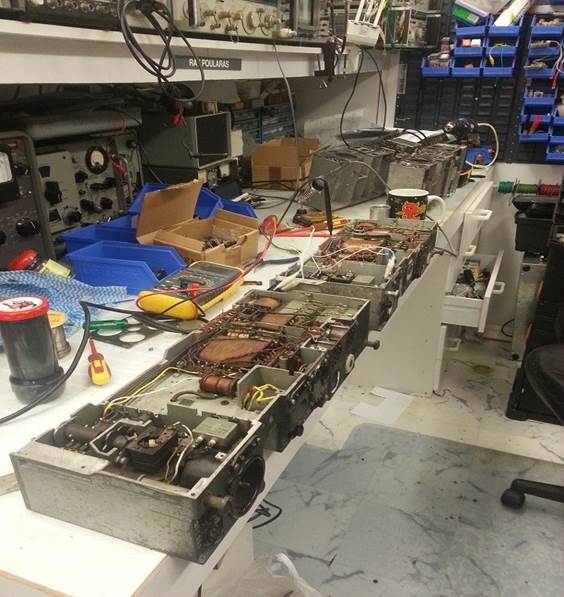
Above
the Bench with candidates Above
is one of the Donor supplies, I used this to transfer all of the Battery
Inverter circuitry
Close up shots of the Donor supply showing the Filter section for the
Inverter supply and the switch section, both were transplanted into a good
chassis.
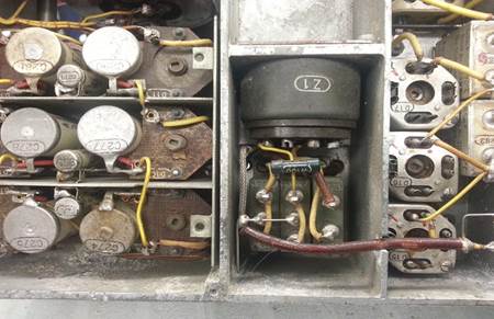
More
closups of the donor chassis.
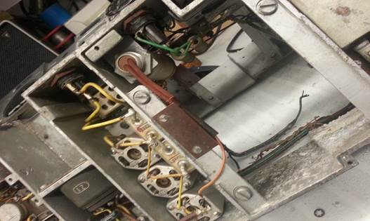
Rebuilding Chassis -1 Rebuilding Chassis -2
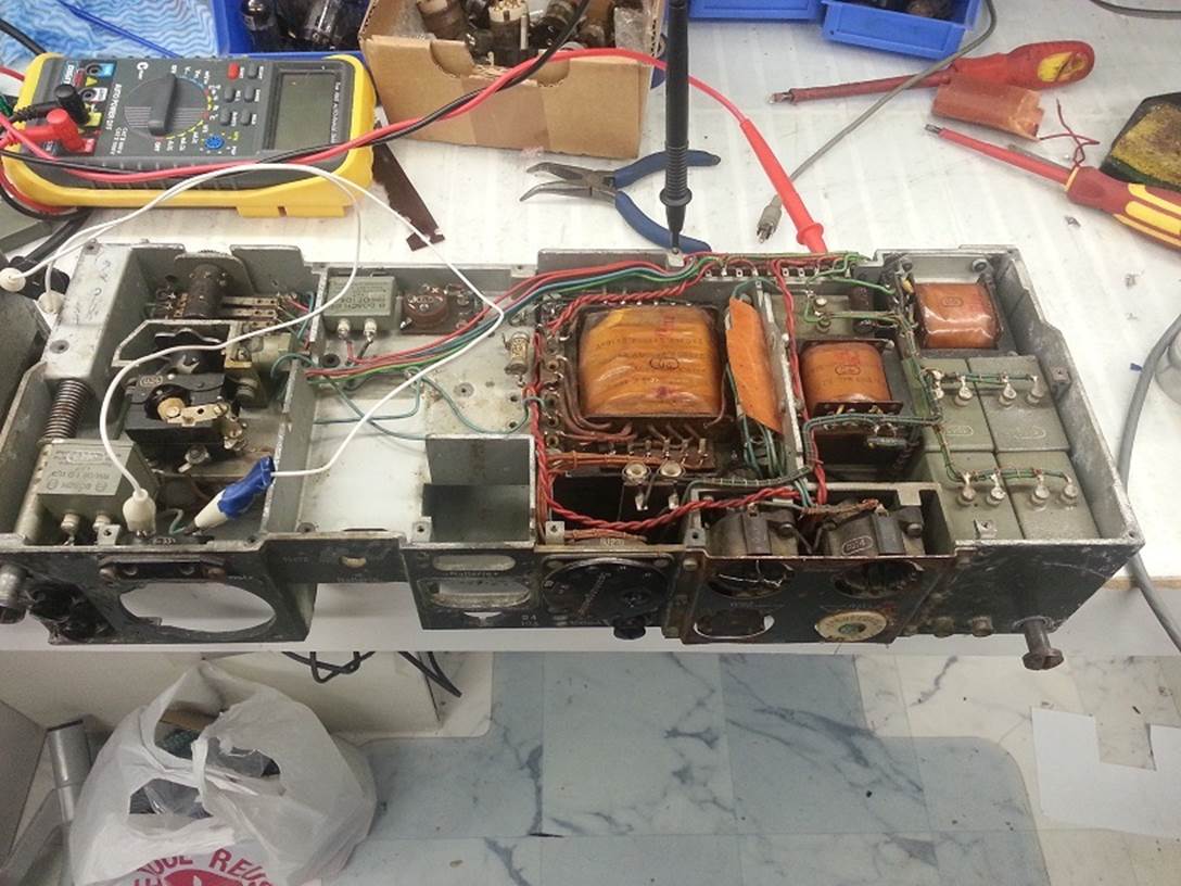
Above Chassis -1 you can see
that there is no Inverter supply as yet, I transferred this from one of the
donor chassis. Also the Power Transformer has been changed, as too the HV
choke.
Note: I found that there are two types of
transformer in these supplies, one has an extra Tap and the wiring is
different. Also note that there is an extra board in the inverter section.

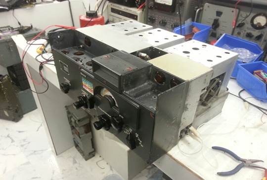
Close Up of the Receiver assembled
and running.
I went through a lot of trouble to do
the full alignment and get everything right. The Receiver performs very well
and has good sensitivity. Area’s I can
improve on are the switch Cams I recast.
I noticed that the switching was not
as good 180 Degrees around from the home position and when I rotated it 180
Degrees again it was great, This is due to uneven cams
and I am working on
A CNC program to
cut 4 new cams from Nylon stock. This should make everything perfect on Receiver Number One,
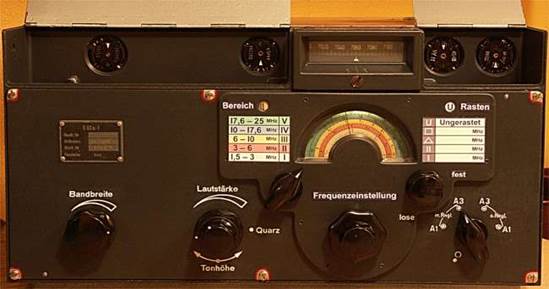
My Second E52B is already restored fine-tuned and runs great although not
as pretty as this one.
Above are two shots of my Second E52, that was
unmolested and in original paint. I rebuild and re-aligned this set and it
operates very nicley. Note that this set has the optional BFO control.
It also differs from the top set by not having the
mechicnisim for Auto Tuning and does not have the split RF gain / Volume
Control.
These small changes were most likely due to material
shortages during production in the war.
Copywright Tube Radio Australia Ray Poularas www.tuberadio.com