Tube Radio Australia
ARB Restoration Project
I first spotted an ARB setup at a Radio Field day. Ray Robinson from
Sydney Australia had his ARB setup with the DU-1 loop and I was impressed with its
operation. It was there and then I decided I needed to get one.
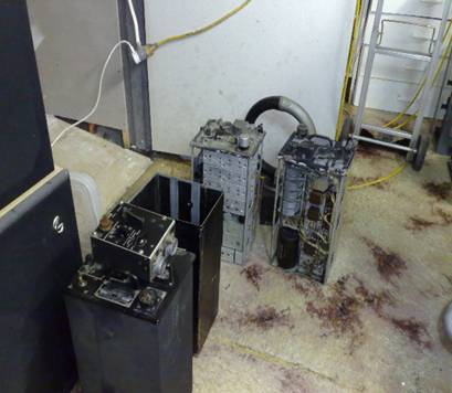
After hunting around online and in the auctions I found two very sad ARB
units. Both had been (Improved), where somebody had hacked them up, removing
there plugs and antenna posts, one even had a mains power supply and holes
drilled in the case for a speaker. Shortly after I found a
DU-1.
The hunt was then on to find plugs and components to fix the units up. A year
had gone by and my ARB projects was sitting on the
shelf as many do when you can find the bits to finish them. By chance I came
across another few ARB units and before I knew it they had started to multiply,
three, four, six, and eight. Then one night the DU-1 stared to do the same,
before I knew it I had three of them. The time had come to build up a few
units. I hunted around and found plugs from Fair Radio and a few other bits
from online auctions. I had enough to build an original setup with a pilot’s
control box; I also will be posting the Navigators box on another unit shortly
and the information and install of the Navy ZB-3 homing adapter.
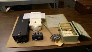
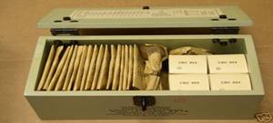
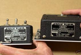
This
Consists of CW-69076 homing adapter w/mounting plate and cloth cover, CW-23214 pilot's
control box w/mounting plate, CW-29173 switching relay w/mounting plate,
antenna N.A.F. 48134-1 antenna, and spares box with complete contents.
Also includes the scarce PLASTIC “Confidential” homing device card. .! Lots of Fun.
Anyway after a few issues with not supplying enough power to the unit I
managed to get the first one running. A dead output transformer and Dyno Motor needed repair and then an alignment. Away we
went. After playing around for a few hours I was DF locating LF beckons all
over the place. Wow really cool on Long wave.
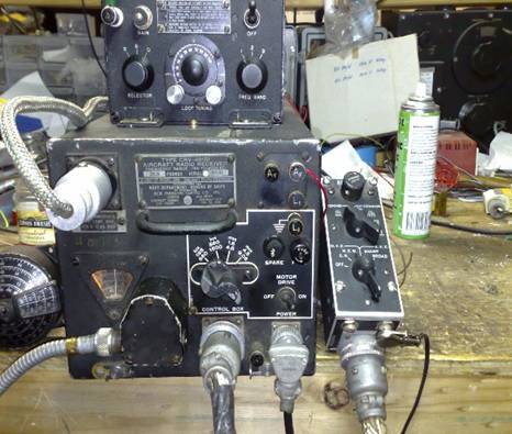
The Front View
before Restoration.
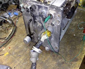
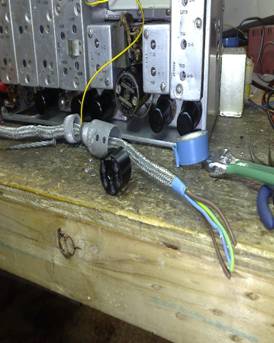
The Front After a cleanup Control Cable in place
Inside top view Dead
Transformer
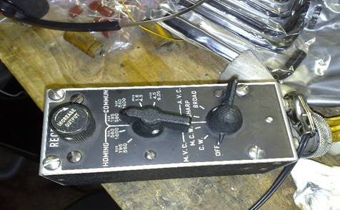
Making the
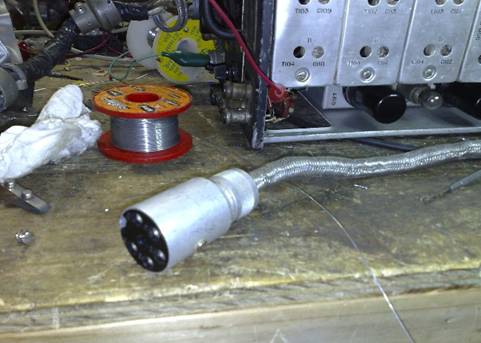
Pilots Control Box Tuning
Head and Drive cable
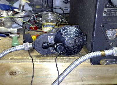
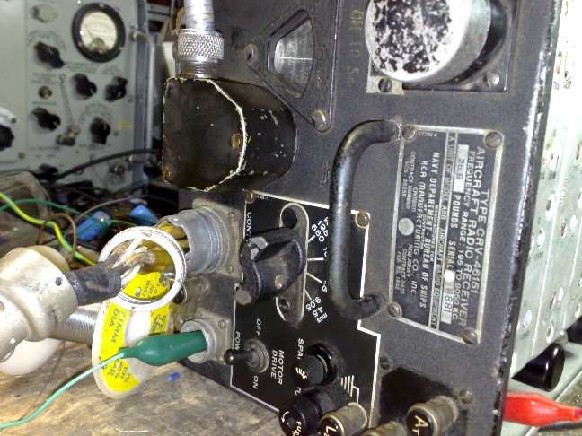
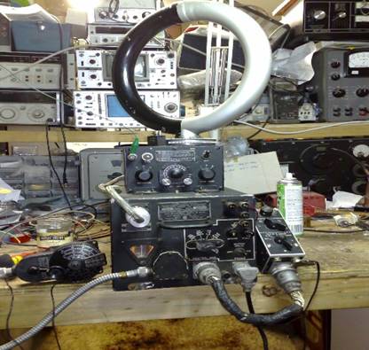
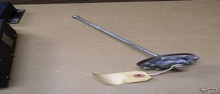
Close up of the
Front Running Loop
Amp on top of the ARB
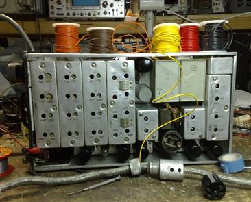
Close up of the
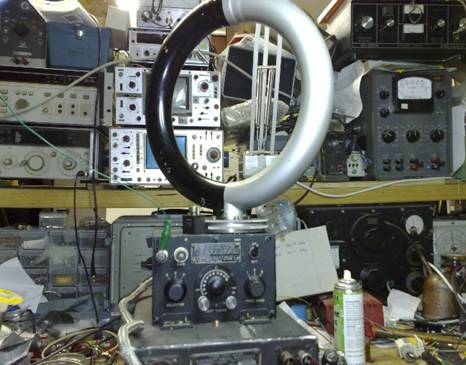
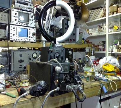
ARB’S
In Waiting ARB’S
In Waiting

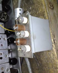
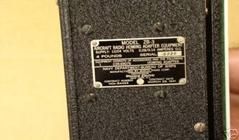
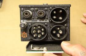
Navy
ZB-3 homing adapter Components, Yes this sits on top of your ARB, he AN/ARR-2
is the combined version of the ARR-1 (also called the ZB-3)
and the BC-946 command set. Used for homing, mainly US Navy.
By Ray Robinson
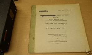
Highly secret, they weren't declassified until 1949.
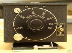
The ARR-1 was a small TRF set covering 234-258mhz,
using acorn tubes, the output was 800-1000khz. This set then connected to the
BC-946
which took the signal and demodulated it to recover a morse signal. The ARR-1 was also used with ARB and
RU-18 receivers, there were 2 studs
on the top of these so it could piggy back, and be powered from the ARB accessories
connector. Also powered from the power adaptor on the BC-946.
The ARR-2 was a combination of these, in a Command set sized box, which tuned
fixed channels, and used minature valves in the font
end.
An aircraft carrier had a rotating aerial, which sent out a different morse character depending on the
direction. When you received that character,
the aircraft knew which direction to turn to locate the carrier.
To prevent the enemy using this system to loacte the
carrier, several ideas were used. The range was small, only a hundred miles at
50,00 feet.
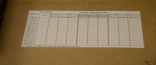
The codes were changed daily, so the pilot neede a
new code sheet every mission. The frequency was high, the
enemy had few receivers capable of tuning
this frequency. The transmitter was only on when aircraft were returning. The
signal was double modulated, so if you had a single conversion receiver,
the output signal would be 1mhz, with modulation on that. Difficult
for an audio stage to amplify, and to hear. The dial was engraved with
the wrong frequency,
the 234-258mhz read
34-58mhz. Although I have seen one with the correct markings, must have been
post war.
73s
Ray VK2ILV

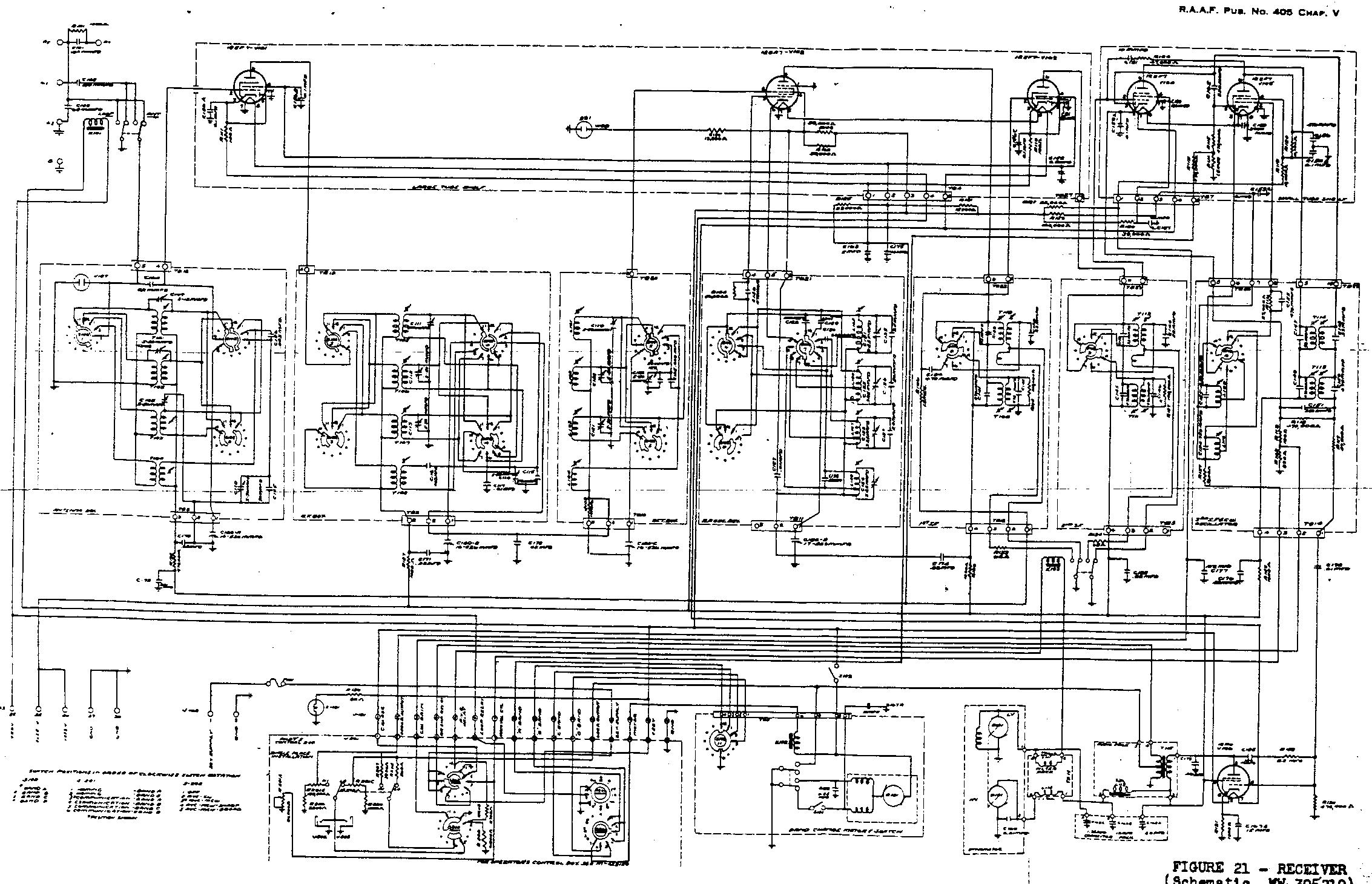
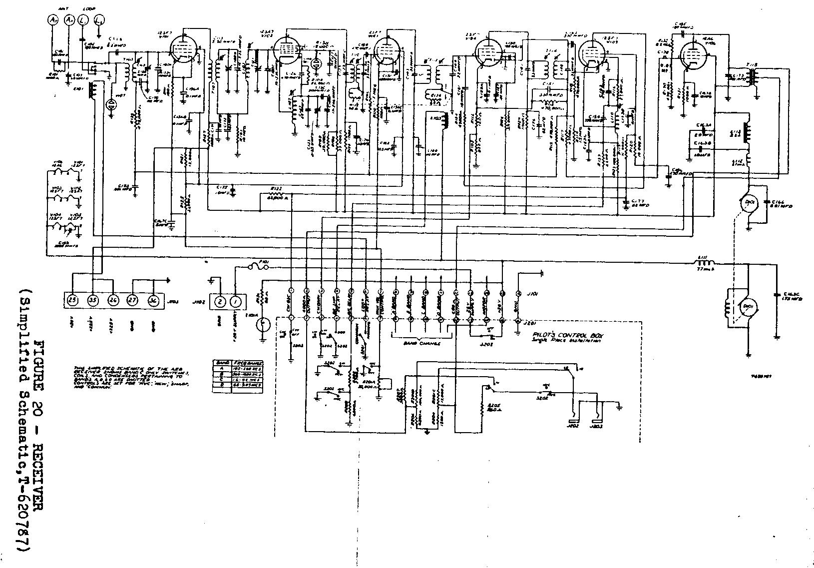
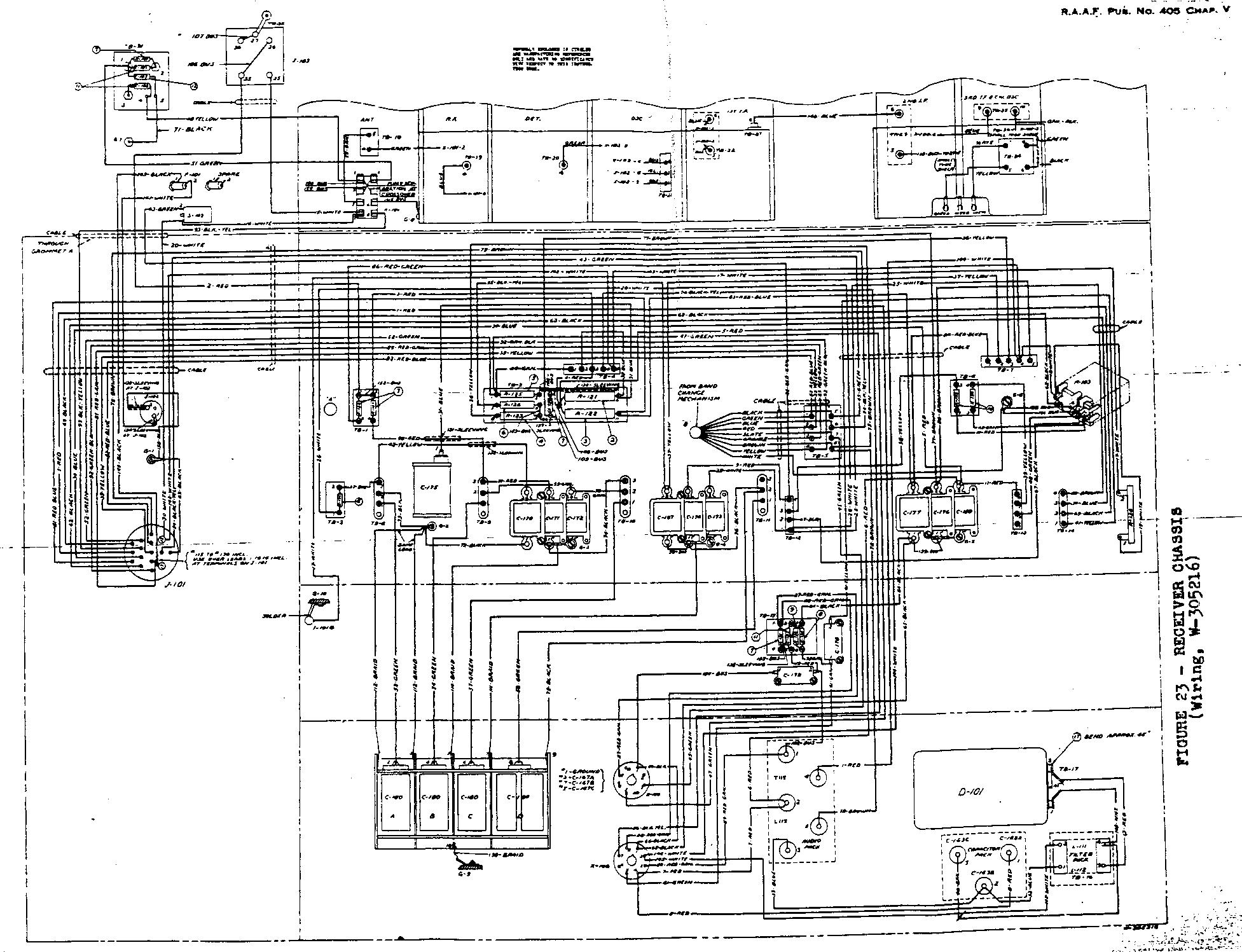
Diagrams and Technical Specifications ARB Set.
Diagram part 1
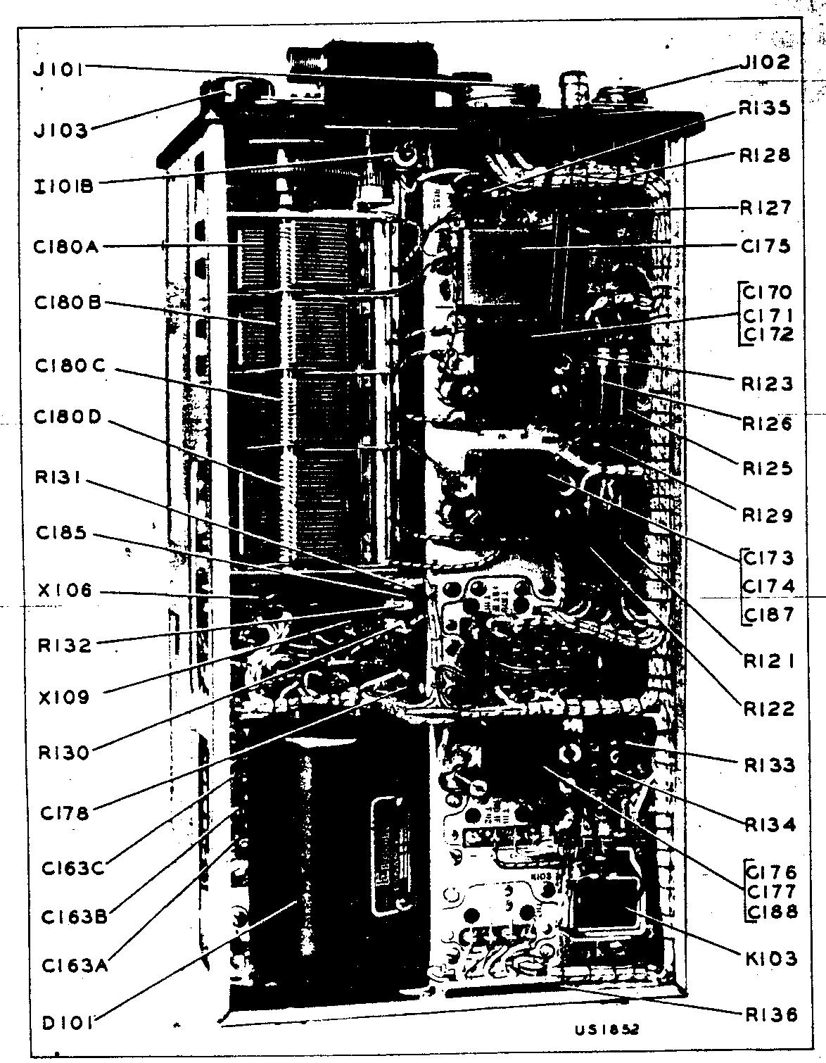
Diagram part 2
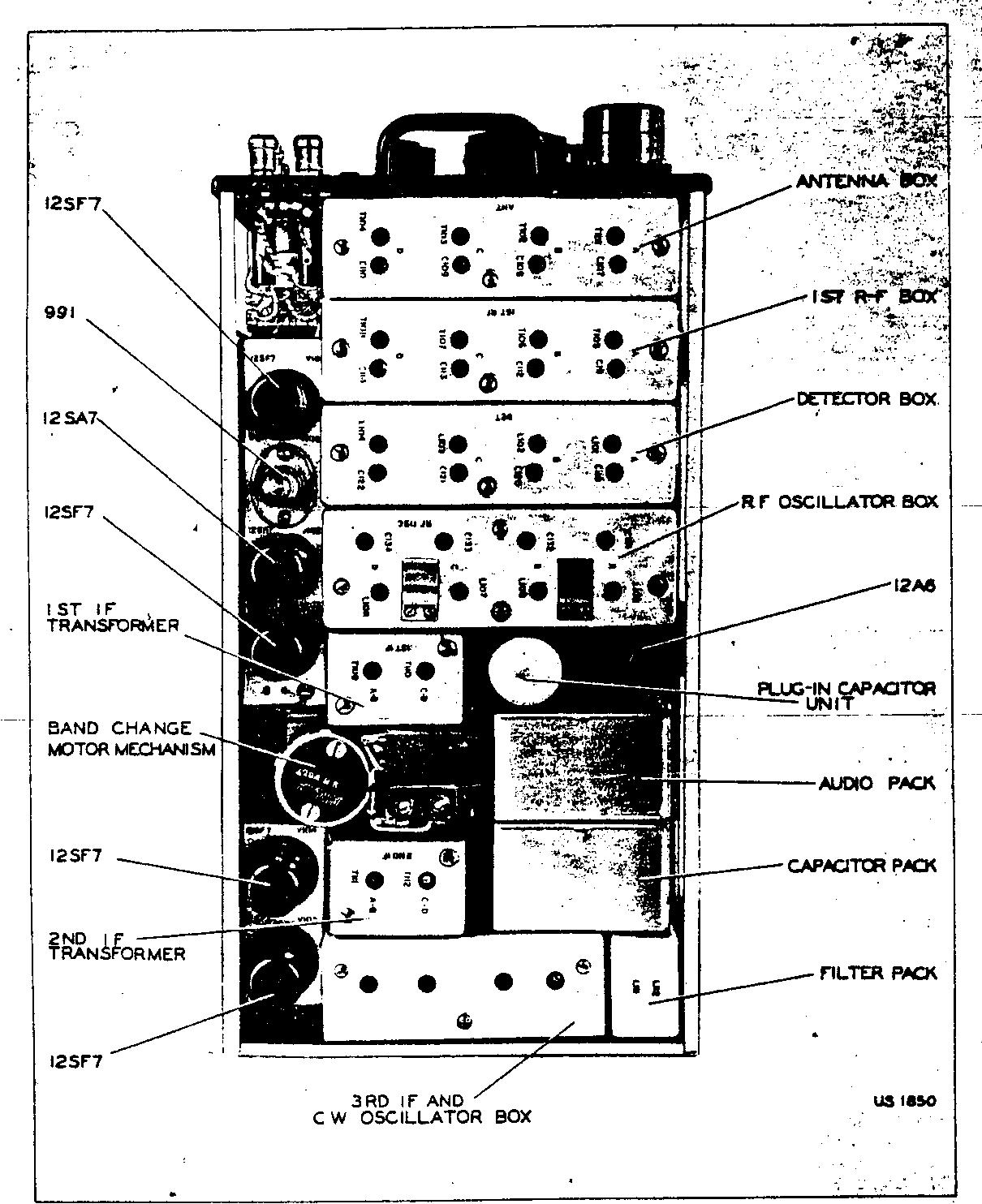
Diagram part 3
![]()