Tube Radio Australia
Zenith Transoceanic Battery
Replacement Project
![]()


![]()
History of this Power Supply
Development
After many years of looking for a commercial power supply that would produce the voltages I needed for Zenith Radio’s the time came when we at Tube Radio had to bite the bullet and design a power supply that meet our requirements. This project is still in the development phase and although we have several working prototypes, we are a little way from having a product to distribute.
Special Thanks to Ray Robinson who worked on the prototypes and did the initial designs.
The first thing we wanted was a stable HV supply, in stating this to produce 90 or 100 Volts DC from 6v or 12v is not that hard. To make this supply provide, a constant 90v or 100v regardless of the battery state and also to make it RF quite is a very different story.
Many supplies today that you can buy from Radio clubs, Ebay or the internet are based on a transistor switching a transformer input, some use a boost technique that only requires a few Chokes but with most the cycle rate is governed by a capacitor resistor network. This means that basically these are unregulated supplies and as the battery changes voltage so does your HV and filament voltage. This can damage you fragile 1,5v tubes and also is not the best for shortwave reception as with voltage change, the frequency of the oscillator will also drift. Nothing is more aggravating then having to touch up the tune every few minutes as the battery drains.
How we addressed this.
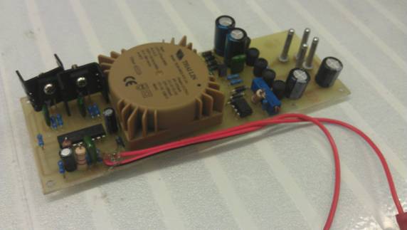
Our power supply utilizes pulse width modulation through a switch mode controller IC. This means that as the battery voltage drops, the pulse width is changed via the controller chip and effectively monitors the output voltage via an isolation circuit to give a constant output voltage until the battery reaches a critical cut of point set as 8 volts. In effect our supply will drain the battery and regardless of the battery voltage the output voltage will remain constant.
Now the pulse width design also brings with it a number of challenges in making the RF quite, as the frequency and pulse width can change with Battery state. This produces noise at differing points across the RF spectrum, and with a moving target makes it nearly impossible to build filtering to counter the effect. After a lot of research and development we have finally build a supply that is quite across most of the bands that most Zenith Shortwave Tube receivers utilize. This includes the AM and Shortwave bands with a RF signal Clock pulse at around 2.5 Mhz.
The Power supply draws 350Ma from a 12V Lead acid battery and with the use of a 6AH battery @ 12V you can run your receiver for a very long time. (DISCLAIMER: Note ! that these figures are with a radio that has had all of the Leaky capacitors and out of specification resistors replaced. If you run a 60 year old radio with vintage parts inside current draw may differ from the specification).
How do I know when my battery is getting
FLAT.
One thing that is unique to the Zenith Radio is that when you’re A+ voltage starts to drop, IE: Filament voltage the oscillator tube will stop working in shortwave mode. You will notice that the AM Broadcast band will still work for a while until the voltage drops below 8V at which time the inverter will shut down.
How does the Power Supply Turn itself on:
The Power supply draws no current when in the off mode. When the receiver is turned ON the power supply senses the current drain on the filament circuit and then starts the inverter circuit. When you turn off your radio the inverter will shut down after 2 seconds, and sleep until you turn the receiver back on.
Current drain on standby is Zero.
Prospective Cost of the final units:
Today the cost in components and assembly is around $150 AUD, the Cardboard Reproduction Boxes are available Ex USA and are around $25.00 so the total is looking to be in the $175 price range @ current exchange rates as of the 20/02/2012. Prices may vary slightly as the exchange rate changes. This is a hobby so I build these for myself and a few to order in my spare time. There are some cheaper options out there but over time with replacement of D cells and Batteries the cost is significantly more over a 12 month period. I use a rechargeable 12V Alarm Battery available from Jaycar or many other electronics’ shops, Led Acid and will charge many times over its life. If you want a reusable supply I think this is the way to go.
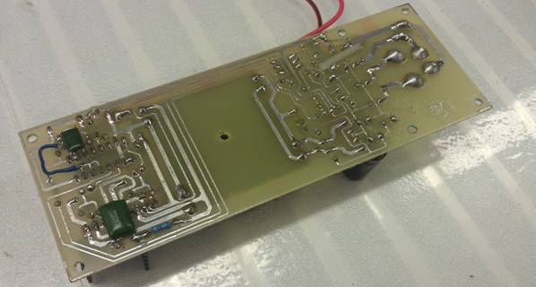
Below are two shots of our early prototypes, the productions power supplies PCB (printed Circuit Board) is and will be a professional tinned PCB.