Tube Radio Australia

The formulas for calculating TFQ dimensions are as follows.
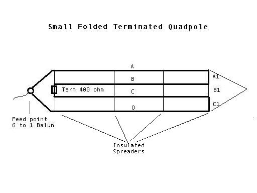
1. The length of each leg ("A,B,C,D'') from the Feed point to the first turn is equal to 50,000 divided by the lowest desired operating frequency (in kHz) and then multiplied by 3.28. The answer is in feet.
2. The spacing between radiating wires ("B") is equal to 3000 divided by the lowest desired operating frequency (in kHz) and then multiplied by 3.28. The answer is in feet.
3. The sloping angle for a nondirectional pattern should be on the order of 30, but 2040 is acceptable.
Example:
To design a QTFD for the center of the 90 meter band (3300 kHz) and up:
Desired frequency
Spacing
Leg "A"
(50.000 / 3300) x 3.28
49.70 feet
Leg "A1,B1,C1"
(3000 / 3300) x 3.28
2.98 feet
Total length of the antenna would be 99.4 feet (2 x 49.7), and the width would be 2.98 feet ("A1,B1 and C1").
The total wire used to complete the loop equals 204.76 feet (4 x 49.7) + (2 x 2.98).