R-744A VHF Surveillance
Receiver
|
Type:
Commercial Receiver (may include amateur bands) |
||
|
Year: 1965 ?? |
|||
|
Valves
/ Tubes |
13: 6612
6611
6611
6611
6612
6612
6611
6611
6611
6611
6611
6611
6611
|
||
|
Semiconductors
(only for transistors) |
1: |
|
Reception
principle |
Superhet with RF-stage; ZF/IF 4300 kHz;
1 AF stage(s) |
|
Tuned
circuits |
8 AM
circuit(s) 9 FM circuit(s) |
|
Wave
bands |
Wave
Bands given in the notes. |
|
Details |
|
|
Power
type and voltage |
Batteries
/ addl. power jack / 1.45 & 45 or 24 Volt |
|
Loudspeaker |
- For
headphones or amp. |
|
Power
out |
|
|
from
Radiomuseum.org |
Model: R-744/PRR
- MILITARY U.S. different makers |
|
Material |
Metal
case |
|
Shape |
Table model,
with any shape - general. |
|
Dimensions
(WHD) |
370 x 139 x 168 mm
/ 14.6 x 5.5 x 6.6 inch |
|
Notes |
U.S.
military communications receiver for COMINT intercept
missions. Also used by Canada and Australia. Used during the Vietnam War.
Frequency range 20-100 MHz AM/FM/CW. Has three RF stages, a two-tube L.O.,
four IF stages, AM and FM det. BFO and one AF stage for headphones only.
There is also a crystal calibrator for every 2 MHz.
Single band: 20-100 MHz continuously with inductive tuning. Two antenna
inputs, normal and DF antenna switch selectable. The four IF stages, FM det.,
BFO, AF stage and crystal calibrator are all plug-in modules for easy
replacement. Each module is made of aluminium and has the size and socket of
a 7-pin miniature tube. All modules contain a sub-miniature tube with all its
components and is sealed. The receiver can be
operated from internal dry batteries or from a 24V vehicle system. The
receivers were made by various manufacturers and exist in some variants. |
|
Net
weight (2.2 lb = 1 kg) |
5.8 kg
/ 12 lb 12.4 oz (12.775 lb) |
|
Literature/Schematics
(1) |
- -
Manufacturers Literature (U.S. Army TM5825-203-20) |
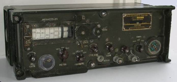
General Notes
This
small receiver was made by Arvin Industries for the US army during the early
1960s. Its dimensions are about 15 x 6 x 7 inches. Coverage is from 20 - 100MHz
in one continuous range and it will receive AM, FM and CW modes. It uses
sub-miniature pentodes types 6611 x 7 and 6612 x 3. Each of the 3 x IF stages,
the calibration and BFO oscillators, AM detector and audio stage are separately
housed in 8 small cylindrical cans about 2" high and 3/4" in diameter
with a B9A tube base. The set is operated either by internal batteries or an
external 24v vehicle power supply. There is no internal speaker, necessitating
the use of headphones.
A
variation seen is the R744(XE-3) made by Mallory,
which doesn't have a band spread knob. These sets were also used by the
Australian Army, where the Contract Number under the makers name has been
blacked out. There is also supposed to be a similar set covering 100 - 200 MHz. These sets were designed as surveillance receivers
having continuously variable tuning to overcome the drawback that most field
military sets were restricted to FM mode with only pre-set fixed frequencies at
say 100kHz separation. The R744 was used in Vietnam
and possibly other fields.
Very
little information seems to be available on the internet about this receiver so
I have posted a copy of the schematics
in djvu format from the manual TM5825-203-20. I can
supply a scanned copy of most of the full manual which is some 2.5Mb in DJVU
format.
 Collectability
These
sets are very scarce in Australia and rarely come onto the market and even seem
to be rare in the US and elsewhere judging by the lack of information on the
internet. Here they would be very collectable and in working order probably a
useful receiver. Their attraction for collectors would be helped by their
functionality and small size in comparison with most military receivers. Only
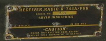
low serial numbers have been seen. The two earliest sets, including this one,
have R-744A/PRR as ID and have S/N 12 and 15 whilst the later models, with the
PRR suffix removed, have S/N 22, 59 and 60. I think it likely that sequence
numbering is within a US contract and not across the full range of sets built. I
know of three other sets, 16, 18, 19 all here in Australia.
Current Condition
This
particular set, S/N 15,was in good condition, all be
it all of the electronic modules in the IF, FM, and RF areas needed attention.
Unsoldering the tubes to replace the pencil tubes and re-align the IF
transformers is a very difficult task. The IF transformers
are glued in adjustment so solvent was needed to free them up so they could be
re-adjusted. The adjustments needed to be done with a dummy shield in
place due to the capacitance the shield causes, I made one from a scrap price
of copper tube with two holes drilled to match the IF screws. The other area
that was a challenge was the RF alignment. The Mixer IF can needed
adjusting and is the same construction as the ones in the IF cans.
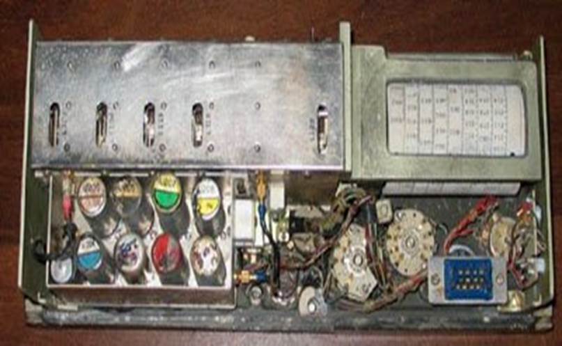
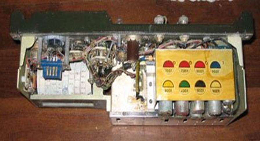
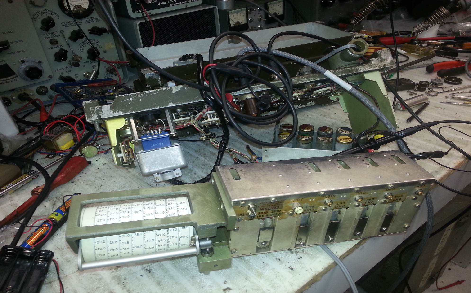
Some Internal Views
RF chassis
removed from the Main front panel so that alignment could be done. Note that
the RF and IF sub-assemblies come away from the Front panel and are only
connected by two RF cables and the power and interconnect plug. Also not that I
am using the optional Power Cable extender from the power supply to the radio
to do repairs, I was lucky that I found a spares case with parts and this cable
in it.
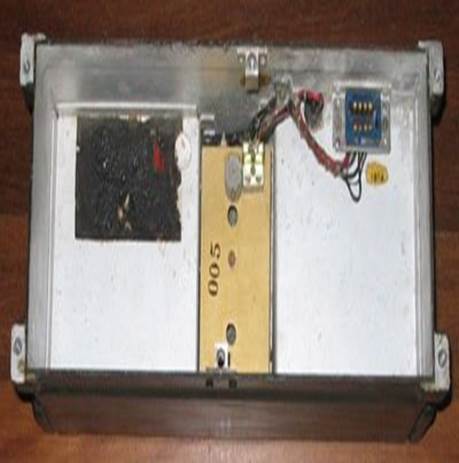
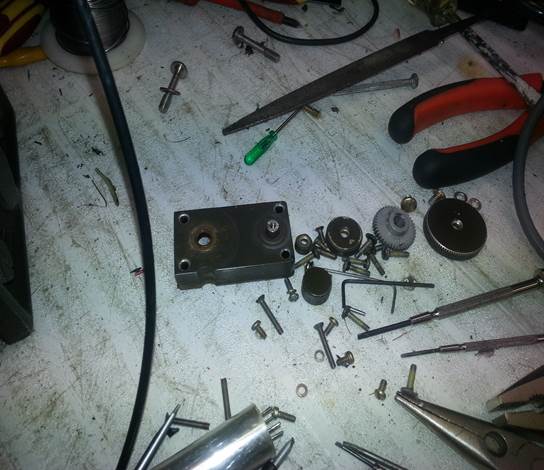
Rear and
case interior with 24v power supply with the Front panel hardware in the third
shot. It was necessary to remove all of this to extract the RF subassembly.
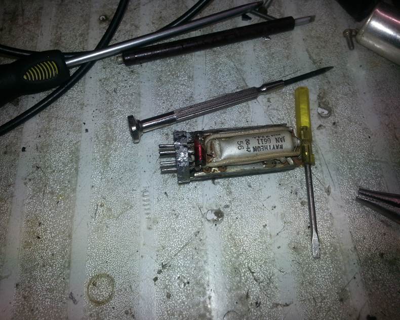
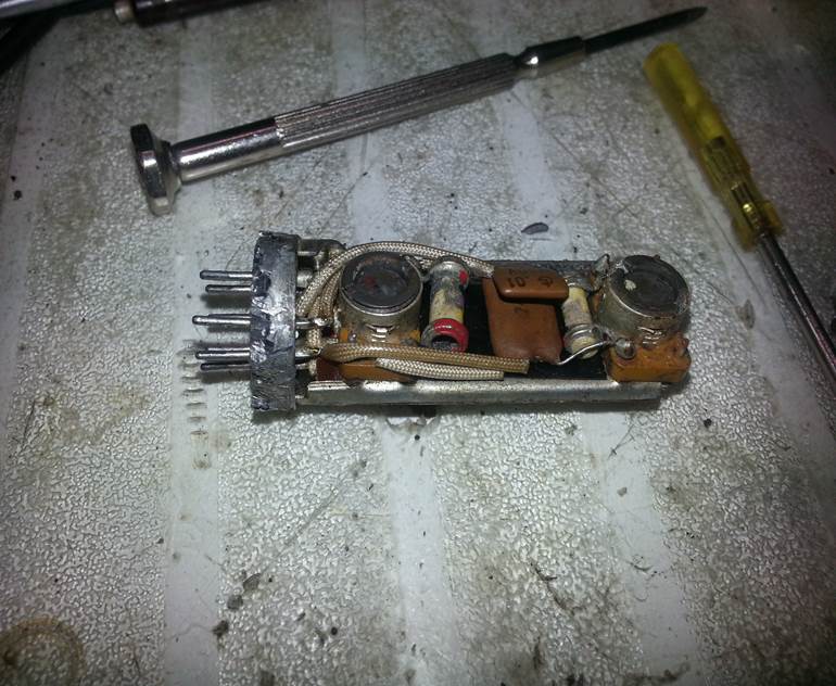
Closeup shots of one of the IF cans.Note the Pencil tube
6611, and on the second shot the IF transformers. You can see the Cores with
slots that needed to be adjusted. Also in my modules a number of the tubes were
damaged and microphonic. They all were replaced.
Assembled
views of the top and bottom: