 | ||
|
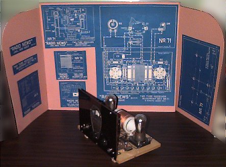
Two-tube radio made a few years ago from plans in the January 1929 issue of Radio News magazine. (Plans designated by Radio News as Blueprint 71) |
The article was titled "The 'Bloopless' One-Dial, Two-Tube Receiver".
The radio is a regenerative design with an untuned RF amplifier stage. The main purpose of the untuned RF amplifier stage was isolation, keeping oscillation from the regenerative circuit from reaching the antenna and causing interference to other receivers.
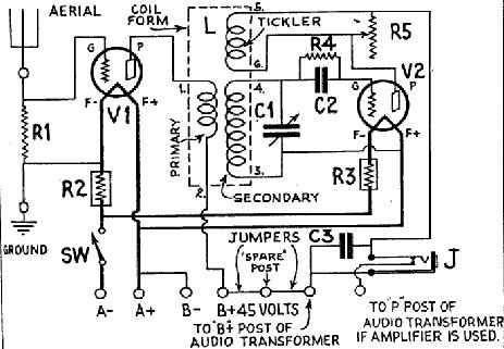
read; many constructors prefer to build from a schematic. The resistor R1 saves
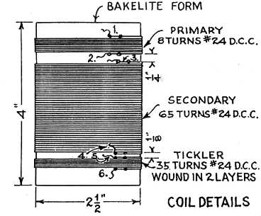
making another coil.