Method
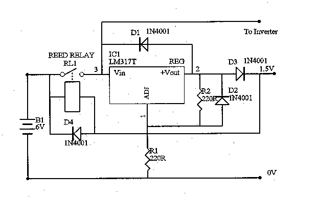
The coil of the reed relay is connected between the battery and the radio's filament input. When the ON/OFF switch in the radio is in the OFF position (switch open), no current will flow through the reed coil and so nothing happens. When the radio is switched ON, the filaments are connected in series with the reed coil. The filaments are a low value resistance, and will draw enough current to activate the reed, but the filaments will not light up. The relay will activate and turn on the filament regulator which will supply the correct filament voltage. When the radio is switched OFF, no current will flow from the reed coil to the filaments, and the relay will switch the regulator off.
A reed relay in a 14 pin IC package has one make contact which can carry 500 ma and a reed coil of 500 ohms resistance. It is also cheap and small. These are used for TTL switching tasks. It will activate at about 3.5 v and can go up to about 7 v. If you have a higher battery voltage, put a Zener diode in series with the coil, to keep the voltage within these limits. For example, if your battery voltage is 12 v, use a 6 v Zener diode.
When the radio is OFF, if you measure the voltage at the filament terminals, you will see the full battery voltage (for example 6 v), in series with the reed coil (500 ohms). When the radio is switched ON, and assuming one valve (for example a 1T4) the resistance will be 28 ohms or lower, and so there will be less than 0.3 volts across the valve. For more valves the voltage will be lower. So there is no danger of damaging the filaments.
The regulator is connected to the filaments as well, but through a diode (to protect the regulator). So the diode must be large enough to carry the full filament current, and the regulator must be set at a voltage to allow for the voltage drop across the diode. If we assume a 0.7 v drop across the diode, and a 1.5 v filament voltage, the regulator should be adjusted to 2.2 volts.

Testing
I have tested this circuit with an LM317 regulator set to 2.2 v and a 6 v power source. As a load, I have used a rheostat and set the current at various values, from 50 ma to 500 ma. I have run this continuously for 24 hours. I have also had a timer circuit (555 timer IC and a relay) that turned it on for 1 second and off for 1 second, for 48 hours. It continued to function OK. I only managed to damage the circuit, when I put a large capacitor on the input of the regulator (100 uF) which welded the reed contacts together with the high charge current. The circuit doesn't need this capacitor. The circuit didn't fail, it just wouldn't switch off!
Conclusion
The advantages of this circuit are that you can use the radio's ON/OFF switch to turn the filament volts on (and the HT inverter) without modifying the radio. There is no current drain when the radio is switched off.
The disadvantages of
this circuit are:
1/. you can only switch
500 ma. If the load is more than that, then you need to use the reed to
activate a larger relay with heavier contacts. There is a dual make contact
reed DIP relay but it has a 200 ohm coil and so draws more current.
2/. beware of sudden
inrush currents (like large capacitors) which can damage the relay contacts.
3/. The battery voltage
must be above 4 volts.
End