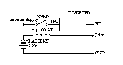
An inverter power supply can be controlled automatically with a reed, sensing the filament current.
When a valve radio has an inverter to supply the high tension, but uses batteries for the low tension, it is difficult to turn the inverter on and off conveniently. Unless it is turned off, when not required, the quiescent current will drain the battery over time. It is not always easy or desirable to modify the radio. A circuit to sense the filament current and turn the inverter on is useful. The circuit should draw no current until the radio is switched on. The use of a conventional relay is not suitable, as relay coils are designed to operate on fixed voltages. A relay coil that operates using current is required.
Use a reed relay (which has normally open contacts) to supply the voltage to the inverter. When the reed is open, the inverter is not powered and so there is no current drain. The reed is activated by the filament current.
Method
A low resistance coil is placed between the battery and the radio's filament input. When the ON/OFF switch in the radio is in the OFF position (switch open), no current will flow through the reed coil and so nothing happens. When the radio is switched ON, the filaments are connected in series with the reed coil, which will close the contacts and energise the inverter. When the radio is switched OFF, no current will flow through the reed coil to the filaments, and the reed will switch the inverter off.
A series of reeds are available for use in burglar alarm systems. They are a slim glass tube containing contacts that are activated by a magnetic field. They are intended to be activated by a magnet being in close proximity to them. The magnet and reed are usually placed on a door or window, such that when it is opened, the reed contact opens and triggers the alarm. The reed is usually specified by the contact rating and the activating magnetic field, often in Ampere/Turns (AT). The reeds I have used are 500 ma contacts, 60 AT, and 1 amp contacts, 120 AT. These are inexpensive. There are many others available.
There are two things to consider when winding the coil for the reed, the number of turns and the coil resistance. The number of turns simply depends on the filament current. If the radio draws 1 amp, then you need a coil with 120 turns for the 120 AT reed (in theory). The coil resistance is important. You have to use thick wire to ensure that there is minimum voltage drop across the coil, as it is in series with the battery. If you are using a 1.5 volt battery, then the coil should not loose more than 0.1 volts.
I used 0.7 mm diameter enamel copper wire and wound 100 turns on a former, such that it was a close fit to the 1 amp reed. I made it long enough to cover the whole reed up to the end pinches. It used 3 layers with no intervening insulation and then I painted it with clear nail lacquer. It activated the large reed with 1.6 amps (i.e. 160 AT) for a 0.18 volts drop, and the small reed at 0.6 amps (i.e. 60 AT) with 0.05 volts drop. I made a larger diameter coil using an aerial coil former, and wound 120 turns in 2 layers. This coil activated the large reed at 0.6 amps (i.e. 72 AT) for a 0.16 volts drop, and the small reed at 0.3 amps (i.e. 36 AT) with 0.10 volts drop. I found that with the larger diameter former, the voltage drop was greater due to the larger amount of wire used. I also found that the AT requirement, to activate the reed varied with different coil designs. There are a variety of reeds available. The Radio Spares catalogue lists the 6RSRA which has 0.5 amp contacts and 40 AT activation, and the DRG200 which has 1.3 amp contacts and 80 AT activation. These are considerably better than those I used in the tests.
Testing
I have tested this circuit using a power supply with an adjustable current limit, with the current set to just above the reed activating threshold. I have used a lamp as a load. I have run this continuously for 24 hours. I have also had a timer circuit (555 timer IC and a relay) that turned it on for 1 second and off for 1 second, for 48 hours. It continued to function OK.
Conclusion
The advantages of this circuit are that you can use the radio's ON/OFF
switch to turn the filament volts on (and consequently the HT inverter)
without modifying the radio. There is no current drain when the radio is
switched off. The disadvantages of this circuit are that there is a voltage
drop across the relay coil.

End