A loop aerial can be simply made from copper tube.
Some radios require a balanced loop aerial for direction finding. The Marconi R1155 receiver used in bombers during the War, had a loop aerial as part of its homing facilities. The loop is also a small convenient aerial for indoor use. Finding a genuine loop is difficult, and it may be necessary to make your own. The specifications are not critical, and a loop is fairly easy to make if you have some basic metal working tools.
A loop consists of several turns of wire, supported in a structure that can rotate.
At your local plumbers supplies you can buy annealed copper tubing which is used by plumbers for connecting things that are in odd places or that don't line up easily. The copper tube has been heat treated so that it is soft and it is wound in a coil. It comes in various sizes and any size will do, but the larger diameters are easier to thread the wires through. I used the 3/4 inch diameter size, and bought enough length to get two loops from it, that is, I bought 2 turns of 3/4 inch annealed copper tube. The shop measured it for me, cut it, and charged me accordingly. Not very expensive. I also bought two T joiners, and 1 foot of straight 3/4 inch copper tube.
I cut the coiled tube so that I had complete circle with a 2 inch gap. In the this gap, I soldered the T joiner, which completed the circle. I then soldered a 6" piece of straight tube to the T joiner, and now I had a circle, with a small handle coming out radially, which is the axis used to rotate the loop. This now looks like a loop, but won't work, as the complete circle is a shorted turn. Cut it at the top (apposite the axle) and widen the gap to 1 inch. This will be used to thread the wire through, and it can be waterproofed after we are finished. To waterproof it, cut a 3 inch length of garden hose (insulating) that will fit snug inside the tube. Chamfer the internal edge of the hose so that the wires won't catch when threading them. Put the hose inside the tube at the gap, and slide it most of the way in, so that the gap is still open for threading, but leave a little of the hose visible so that we can slide it to complete the gap when finished. Now thread a piece of insulated wire, up the axle around the loop, as many times as you can, then back out though the axle. The type of wire used is not critical, but it must be insulated. Check it for short circuits to the copper tube when you are finished, and if there are any, strip it out and rewind it. I could only fit 6 turns in my loop, but it worked fine. Slide the hose to fill the gap and glue it in place, so that it is weather proof. It also adds a little strength to the loop. Connect the ends of the wires from the loop to a receiver and test it. It should work properly and be directional. With the axis vertical, rotate the loop, and the received station should be loudest when the plane of the loop faces it, and it will be broad. Rotate it some more and the received station should be softest, when the edge of the loop faces it, and it should be sharp (a null).
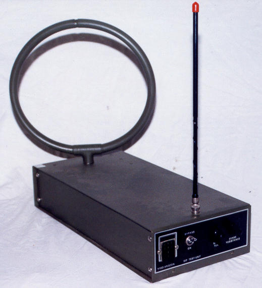
Now mount the loop. I used a stereo phone plug as the connector (tip/ring/sleeve), and connected the loop turns to the tip and ring, and the loop copper pipe to the sleeve. I then fitted the phone plug into the axle with some packing and some grub screws. I used a phone socket as the slip rings so that the loop can rotate. I made a box with the phone jack and some support for the axle so that it can rotate. I then made a larger loop but could determine no increase in signal or directivity. The loops plug in. I painted it green.
The impedance and inductance are unknown. It seems to resonate at 6 mcs but I am using it at 200 - 500 kcs. The R1155 manual goes to some trouble to get it to work as a combination with the sense aerial, and provides some scant information on inductance and cable lengths for correct matching. The phase of the signals is important. I just used it as is, and it crudely works.
The "sense" aerial is the normal long wire aerial of the aircraft. Since I don't have one, I used a small whip. There was little gain, so I built a little IC ampifier. It is not very good, as ideally it should be broad band but the broadcast stations overload it. I had to fit a tuned circuit in the to remove the strong stations and tune the desired one, but this appears to affect the phase, and while it works, it is unreliable and difficult to get good results.
The loop works well on the R1155 and gives good D/F for "Figure of Eight" but the sense or "Visual" is very unreliable, due to the amplifier and whip.