GENERAL FAULTS
The faults can be loosely categorised in two groups.
Failures and age.
If it was the year 1950 and your near-new radio has stopped, you would
look for a failed component.
However, the radio is now over 50 years old, and age will affect many
parts, so age effects will need to be corrected first.
The radio may have failed in 1950 and been put on a shelf, so you may
possibly have several faults, the original one, and the age effects.
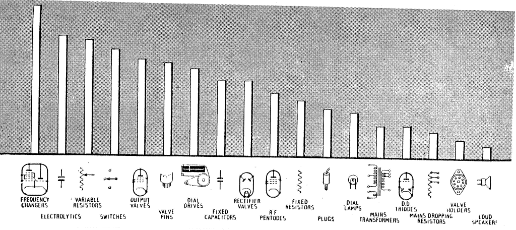
There is a histogram from Radio and Hobbies that shows the common faults
in 1959. This is very interesting and useful, but it applies to near-new radios that were in use at that
time and failed.
Valves account for less than 10% of faults.
Most faults are due to capacitors, particularly filter capacitors,
bypass capacitors, and coupling capacitors. I usually don't bother to
even check the valves. I go straight to the capacitors, and if they are
in poor condition, I will often replace all the paper capacitors and
electrolytic capacitors, even before powering a radio up. If the capacitors
look good, I will still check the electrolytic capacitors and the audio
decoupling capacitor (especially this one).
Sometimes I will check the resistors, but unless they look burnt,
I leave them alone.
Fading: If the radio works, then slowly fades away,
then slowly comes good again, it could be an intermittent connection
to a valve heater, causing it to warm up then cool down. Check for a
dry joint on the valve socket, or a dirty socket.
For instability, check shielding, particularly the
I.F. amplifier. Sometimes corrosion on the shield rivets or bolts means
they are not earthed.
If the radio produces a funny burping sound (called
"motorboating"), it is usually feedback between stages, coupled by the
HT or AGC line, so suspect faulty screen, high tension or AGC bypass capacitors.
This may only happen at high volume control settings.
If the radio appears to be working but there are
no stations, scratch the aerial wire with a screw driver or to chassis.
If a scratchy noise is heard, then the mixer oscillator is not working
or is off frequency.
If the radio produces a rattling or tinkling noise when
it is bumped, it may be "microphonic" which is usually due to loose electrodes
inside a valve. Lightly tap each valve with a finger to determine the faulty
one. Replacing the valve is usually the only way to cure this. If the valves
were of a microphonic type when made, the valve base may be sping loaded
or on rubber. Check and renew the rubber mountings.
POWER SUPPLY
The power supply normally consists of a transformer, rectifier,
filter choke and filter capacitors.
The secondary of the transformer, is usually a centre tapped winding
with 250 volts AC per side. The two ends are connected to the rectifier
plates, to provide full wave rectification. A separate heater winding
of 5 volts AC is supplied to the rectifier (type 5Y3). This is where the
rectified voltage appears and there is a smoothing filter capacitor of
usually 8 microfarads rated at 350 volts DC. The high tension then flows
through a smoothing choke, to another filter capacitor. In newer radios,
there may be a high wattage resistor used as the choke. This can burn out.
In older radios, the speaker used an electromagnet, so this winding was
used as the filter choke. In these radios, there is a large voltage drop
across this coil, so the rectifier supplies about 400 volts DC, and the
capacitor is rated at a higher voltage. There is usually a separate heater
winding of 6 volts AC for the remainder of the valves. On more modern radios,
a new rectifier was used (type 6X5), that had a separate cathode (with a
high isolation between cathode and heater), so that only one heater winding
was required on the transformer.
Check the voltage across the filter capacitors for about 250 volts
DC.
Common transformer faults can be: burnt out (replace or
rewind the transformer), open circuit (replace or fix), buzzing (tighten
the clamps or screws, or if a short circuit is causing this, remove it).
If open circuit, determine which winding. Sometimes the tinning or soldering
process can break a wire where it enters the transformer. This can sometimes
be carefully rejoined.
Common rectifier faults can be: burnt out (replace the valve), sparking
(check for a short circuit in the high tension line).
The rectifier valve should have a dull glow for the filament or
heater. If the plate is glowing red, then there is a short circuit on
the HT line. Turn it off immediately and locate the short.
Common filter choke faults are: open circuit (replace or look for
broken wire or damage), or short circuit to choke body (insulate the
short). Chokes can be rewound.
Common filter capacitor faults: open circuit (replace), short circuit
(replace), low capacity (replace), hot (turn OFF quickly, and keep trying
each 24 hours, they may reform), exploded (clean the mess and replace).
There is a less brutal method of reforming filter capacitors, by limiting
the current to them, by using a high value resistor, until they recover.
To reform a capacitor, place a 470k resistor in
series with the capacitor and apply 250 V DC. Measure the voltage across
the capacitor. When the capacitor "reforms", the voltage will be the same
as applied. While the capacitor is reforming, the voltage will slowly climb
from zero to the voltage applied. If the capacitor
gets hot, turn it off, and try again each 24 hours, perhaps for
as much as a week.
SPEAKER
A speaker consists of a paper diaphragm, with a coil wound on the
apex of it, called a voice coil. The coil is placed in a magnetic field,
and when a current passes through the coil, the diaphragm will move and
produce sound waves in the air. The magnet can be a normal permanent magnet
on modern speakers, but may be an electro-magnet on older speakers. The electro-magnet
coil can also double as a filter choke for the power supply. In this case
there may be a small additional coil connected in series with the voice
coil, called a "hum bucker" to prevent any hum from the electromagnet producing
sound. There may also be a speaker transformer mounted on the back of the
speaker.
In radios with removable speakers (like radio grams or consoles)
the HT line is often routed through the speaker plug with a link,
to prevent high tension being supplied to the radio if the speaker is
unplugged.
Distortion can occur from a torn diaphragm or torn edge
suspension. Repair it with a thin layer of silicone rubber. If
there is dirt or iron filings in the coil, remove them. A pair stainless
steel tweezers (non-magnetic) are useful. If the voice coil is touching
the magnet, called "poling" adjust it if you can. Put a piece of 35 mm
film in between the pole and voice coil as a spacer, and loosen the pole
bolt, adjust and retighten. Alternatively, the edge may be adjustable. Remove
the film.
If the electromagnet is open circuit, find the break,
which is normally near the start or outside. Reconnect and re-insulate.
Even taking off a few hundred turns will not significantly affect the operation
of the speaker or the filter function. H.R.S.A. members can rewind the
electro-magnet, and even recone a speaker, if required.
Check the primary of the transformer with a multimeter
(on the ohms scale). This should cause an audible click to be heard in the
speaker (the radio should be off).
AUDIO OUTPUT
The audio output valve uses a speaker transformer to match the
valve high output impedance to the speakers low impedance. There is sometimes
a small capacitor to ground to prevent oscillation, or it may be connected
to a switch or variable resistor as a Tone control. The screen is normally connected directly to the high tension
supply. The valve needs a grid negative bias, and
this is normally done by a cathode resistor which has a bypass capacitor.
This is called "cathode bias". Another bias method called " back bias" can
be used. This method involves grounding the cathode, and using a resistor
in the power transformer centre tap to generate a negative voltage. There
is sometimes a capacitor connected back to the grid as feedback. There may
also be a resistor in series with the grid as a "stopper" to prevent oscillation.
All of the resistors and capacitors in this circuit can be 50% out of tolerance,
and there will be little change in its operation. A quick check is to touch
a screwdriver to the grid, then touch it with your finger, this will
introduce some hum, and you should hear it in the speaker. To avoid a
possible shock, do not touch the chassis.
If the primary of the speaker transformer is open circuit
there will be no sound, and the screen will be red hot. Turn off quickly.
If the cathode bypass is open circuit, there may be distortion
or low gain.
A crackling noise can be a noisy anode capacitor, or a scratchy
Tone control.
Spray "CRC" or "WD40" into the control, and rotate it back and forth.
If the valve is glowing blue, it may have air in it (be "soft")
and need replacing.
Distortion may be caused by a "leaky" coupling capacitor from the
previous amplifier stage. This is one of the most common faults in all
valve radios. The audio grid should always be zero or negative volts.
Any positive volts means a leaky capacitor. Replace it. It should read
"infinity" on the ohms scale of a multimeter.
Also check that the resistor from grid to earth is not open circuit.
A short between the heater and cathode can introduce hum. Replace the
valve.
Another source of hum can be a faulty filter capacitor on the high
tension supply. Replace it.
If you are really driving the audio amplifier hard, and the speaker
is not connected, there can be arching between the screen and anode pins
on the valve socket. This normally burns the socket and it needs replacing.
The Tone control is sometimes a series capacitor and
a variable resistor control, from the valve anode to earth. The capcitor
can fail in a short circuit, and burn out the Tone control and the speaker
transformer. Sometimes the series capacitor and variable resistor is connected
from the valve anode to the screen. This arrangement reduces the voltage across
the capacitor, but has the Tone control with HT on the control. Be careful.
Sometimes a varible resistor is not used, but a switch and one or more capacitors.
AUDIO PREAMPLIFIER
The audio preamplifier can be a triode or pentode and as the valve
contains the detector and A.G.C. diodes as well, the circuit may appear
complicated. Treat it function by function, and the theory is not too
difficult. The anode of the valve is connected to the high tension supply,
and a capacitor from the anode, couples the audio to the power amplifier.
Sometimes there is a small capacitor from the anode to ground, to ensure
none of the IF gets into the audio to cause instability. The volume control
wiper takes the detected audio to the grid of the preamplifier. There is
usually a grid resistor to ground, and a coupling capacitor from the volume
control. These seldom fail. The cathode may either have cathode bias or be
connected to ground.
A quick check is to touch a screwdriver to the grid, then touch
it with your finger, this will introduce some hum, and you should hear
it loudly in the speaker. The grid may be the top cap (in an older radio)
or the wiper of the volume control.
A crackling noise can be a noisy anode capacitor to
ground. Replace it.
Sometimes the anode or screen resistors can be open circuit, causing
no sound. An out of tolerance resistor is not a problem.
If sound can still be heard when the volume control is, turned
all the way down, the cathode bypass capacitor may be open circuit.
Replace it.
The valve rarely fails.
DETECTOR
One of the diodes in the audio preamplifier valve is used as the
audio detector. The top of the secondary of the last IF transformer
is connected to the diode. The rectified audio appears between the bottom
of the IF transformer and the valve cathode. This is then coupled to the
volume control. Usually there is a filter circuit consisting of a resistor
and two small filter capacitors, to smooth the audio and remove any I.F.
component before it gets to the volume control. The bottom of the volume
control may be connected to ground or the cathode. There is little to
fail in this circuit, and faults here are uncommon.
An open circuit IF transformer can cause the audio to fail, but the AGC may still function.
AUTOMATIC GAIN CONTROL (AGC or AVC )
The second diode in the audio amplifier valve can be used as the AGC
rectifier. The diode is connected to the anode of the I.F. amplifier
by a capacitor, so that it does not cause audio distortion. There is
a resistor to ground from the diode, which is the diode load, and the
negative voltage is developed across this. The stronger the signal, the
higher the negative voltage. This is coupled forward to the grids of the
I.F. amplifier to reduce its gain on strong signals. The AGC is sometimes
connected to the mixer grid as well, but this may cause unwanted frequency
change to the oscillator. In domestic sets this is not critical. In communications
receivers, the audio preamplifier may also have AGC applied. The AGC
line has large capacitors and large resistors to connect it to the preceding
stages. These reduce the voltage as it goes forward and prevent any coupling
which may cause oscillation. High value resistors can be tolerated.
A leaky coupling capacitor can cause positive voltage to
appear on the AGC diode, and so generate a positive AGC voltage. Replace
the capacitor.
Open circuit capacitors can cause instability. They may also
cause the AGC to act too fast. Typical AGC voltages are , -2 volts for
normal operation, up to -30 volts for strong stations.
"Leaky" can mean several things. Usually, a healthy capacitor has no
DC path through it, but as the internal dialectric breaks down due to age
or overvoltage, it can have a DC resistance of 100k ohms or less. This means
that DC will "leak" through it. Secondly, a capacitor may fail or overheat,
and fluid may literaly "leak" out of it. Thirdly, there is an audio detection
circuit that uses a capacitor and resistor in parallel, and is called a "grid
leak" detector, but this is not a failure mode and is normal circuit operation.
I.F. AMPLIFIER
This amplifier is the most important amplifier in the radio, as
this is where most of the gain comes from. It can also be where the most
instability is found. Good shielding and bypassing is essential. Sometimes
this amplifier may have "negative" feedback or "neutralising" on it,
to make it stable. It is a simple amplifier, with a tuned circuit on the
input and output. It often has cathode bias, and always AGC control.
The tuned circuits act like a filter to reduce reject adjacent signals,
and to ensure the local oscillator is removed. The I.F. transformers can
be tuned with a signal generator. They may also tuned by ear, if you are
careful and use a weak signal, to make the tuning sharp and to make sure
the AGC has no effect. Sometimes resistors and capacitors are conveniently
(or inconveniently) mounted inside the I.F. transformers.
Common faults are mis-tuning of the tuned circuits, open
circuit windings (broken wires) or broken slugs.
If the I.F. amplifier tunes up correctly, and then suddenly looses
sensitivity when you turn it upside down, the slug is probably broken
and moving around freely inside the I.F. transformer. Most radios have
fixed capacitors and ferrite slugs to tune them. Some older ones may have
variable capacitors. In this case, use an insulated screw driver to adjust
them as there will be HT on them. Don't short them to earth.
Instability can be due to faulty bypass capacitors or failed shielding
due to corrosion.
MIXER
The mixer (sometimes called the first detector) is usually a valve
that has many screens, or it may have a separate triode inside. The screens
or triode act as an oscillator. The oscillator has its own tuned circuit
and tuning capacitor (part of the main tuning capacitor). The oscillator
normally runs at a higher frequency than the received station, and the
difference is always the I.F. frequency. The oscillator in this way, selects
the desired station, for the I.F. amplifier. The oscillator signal is mixed
with the received signal inside the valve, and the coupling is by virtue
of the components being inside the same valve. Communications receivers
that have a separate oscillator valve, require a coupling capacitor to
inject the signal into the mixer. The settings of the stations on the dial
is achieved through adjusting the oscillator.
The aerial signal is connected by a tuned circuit to the mixer grid. There may be AGC connected to the bottom of the tuned circuit. The main tuning capacitor has a separate section to tune in the stations. Each tuning capacitor section has a "trimmer" capacitor across the main capacitor to adjust the frequency of the tuning, but this trimmer only has an effect when the gang is nearly fully open, that is, at the high frequency end of the dial. There is sometimes a "padder" capacitor in series with the main tuning capacitor, but this padder only has an effect when the gang is nearly fully closed, that is, at the low frequency end of the dial. If a padder is not fitted, then the tuning can be adjusted with a ferrite slug inside the coil. Use this at the low frequency end of the dial. Always adjust the low frequency end first. Re-checking and readjusting, may be required several times as they interact.
If the radio appears to be "live" by scratching the aerial
terminal or grid with a screwdriver and causing a noise, but there are
no signals, the oscillator has probably stopped. A weak or low emission
valve is often the cause. Try another known good valve.
A negative voltage on the oscillator grid means it is oscillating.
This is hard to measure, as touching the grid with a multimeter or oscilloscope
probe can often cause it to stop. One sure way to check, is to lift the
earthy end of the oscillator grid resistor and check for negative grid
current. It will be a few micro amps. If no current, then it is not oscillating.
If the stations do not agree with the dial, first check the dial
pointer and dial scale, and mechanically move it, if necessary (or possible).
Only then, adjust the oscillator if further correction is needed. Always
set the low frequency end first.
If dial readings cannot be set, check the trimmer and padder capacitors.
Also check that the oscillator is on the correct side of the received
frequency. Some communications receivers, have the oscillator on the high
side for the low bands, and then change to the low side for the high frequency
band.
Common faults can be burnt aerial coils due to lightning
strikes. Also broken slugs and capacitors from previous attempts to repair
or tune the radio. Look for bent tuning capacitor plates, or corrosion
"whiskers", if the radio only works for half of the dial. Check for open
circuit coils and I.F. transformers, and open circuit resistors.
If the radio is a dual band radio, check the band change switch
and clean it if necessary. Poor performance on short wave is often caused
when a wrong type mixer valve is fitted.
Broken dial cord can be restrung with fishing line (if really necessary),
but it slips on small diameter shafts. Real dial cord can still
be purchased from WES.
If AGC is applied to the mixer stage, through the bottom of the
grid coil, the tuning gang may be insulated from the chassis with rubber
mounts. These may be old, brittle or missing, rubber grommets are a suitable
replacement