The AR7 is a communications receiver covering LF and HF bands. It was made in Australia during 1940 and bears an extremely close resemblance to the National HRO receiver. The receiver has a tuning range from 138 kcs to 25 mcs, with a gap of 45 kcs either side of the 455 kcs IF amplifier. The internal design is a single conversion superheterodyne receiver with 2 RF stages, 2 IF stages, a BFO and an "S" meter amplifier. The sensitivity is quoted as 1 microvolt. The front panel is stainless steel and it is a very distinctive looking receiver.
It is a good performer, sensitive, has a nice feel, is easy to tune, but hard to find the correct frequency, by reading the frequency from the dial number and coil box graph. It really needs a crystal calibrator. I use it for the weekly W.I.A. (Wireless Institute of Australia) broadcast, so it gets turned on once a week, and is so stable, than I don't have to retune. It is very clear for AM but a bit fiddly for SSB.The controls are: RF gain, BFO note, AVC/BFO switch, Adjust "S" meter, Tone, Tuning, Noise limiter, Selectivity, Crystal IN/OUT switch, Crystal Phasing, Audio gain. The Audio gain control has an OFF position which removes the HT so that the coil boxes can be changed.
It has two 6U7G RF stages, a 6K8G mixer, two 6U7G IF stages at 455 kcs, a 6G8G detector/AVC/audio preamplifier, and a 6V6G audio output amplifier. It has a 6C8G twin triode as a BFO and "S" meter amplifier. It also has a crystal filter. The IF alignment should be done very carefully, as any misalignment will reduce the effectiveness of the filter. It is best done with a sweep generator. The 6 volt valve heaters are connected in series, for 12 volt operation.
The external power supply and speaker, are usually mounted in a short 19" rack, the AR7 at the bottom, the speaker in the middle, and the power supply at the top. The complete unit weighs about 118 pounds. The power supply was switchable between 12v and 240v.
The receiver was used as a ground monitoring receiver for aircraft. It was extremely stable. The model shown has an R.A.A.F. nameplate, and serial number 1786. The manual I have is a D.C.A. (Department of Civil Aviation) version and is a 1947 issue.
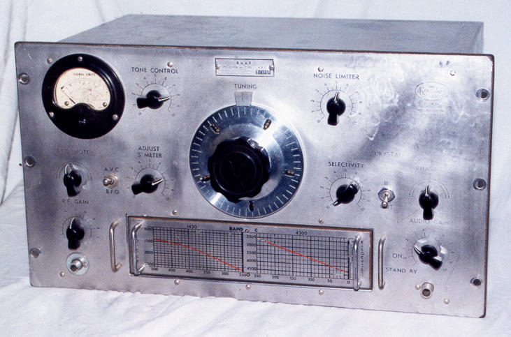
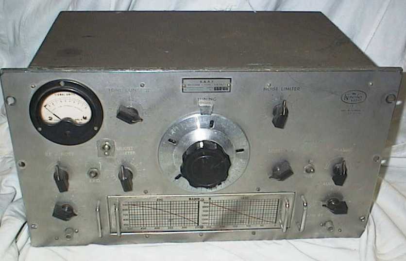
This is a front view of the AR7 with the band C coil box plugged in. The left hand phone jack has had the hole filed out to take a pilot light. I have fitted the original phone jack, but have has to use a washer to cover the hole. Other than that, the front is completely original.
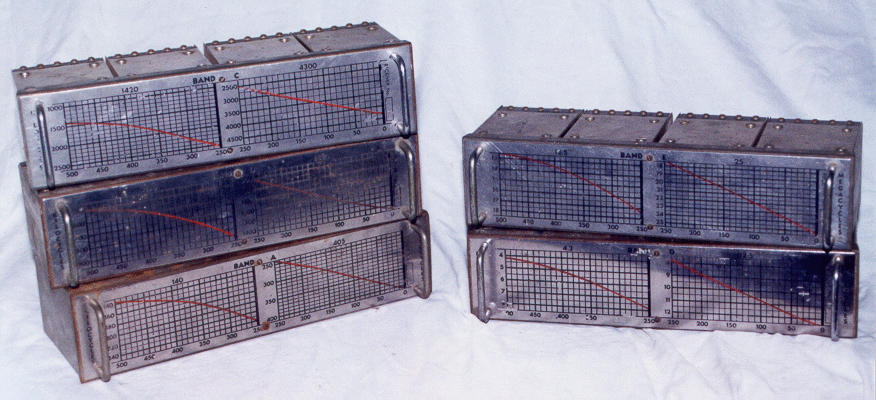
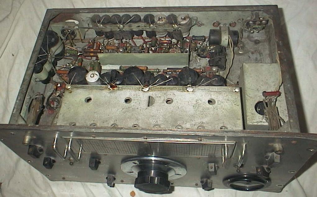
It has 5 plug in coil boxes. The coil boxes are: band A 140-405 kcs, band B 490-1430 kcs, band C 1.420-4.3 mcs, band D 4.25-12.5 mcs, band E 12.5-25 mcs. The Army version had an extra coil box covering 50-150 kcs. The large dial is a 20:1 reduction drive and has graduations from 0 to 500. It acts like a flywheel when tuning across the band, and has an effective scale length of 12 feet. The dial shaft goes into a right angle reduction gearbox and has 2 output shafts that drive 2 dual gang capacitors. The arch of the gearbox and the 2 capacitors are visible in the photograph. The graph on the front of each coil box is used to covert the dial reading to frequency.
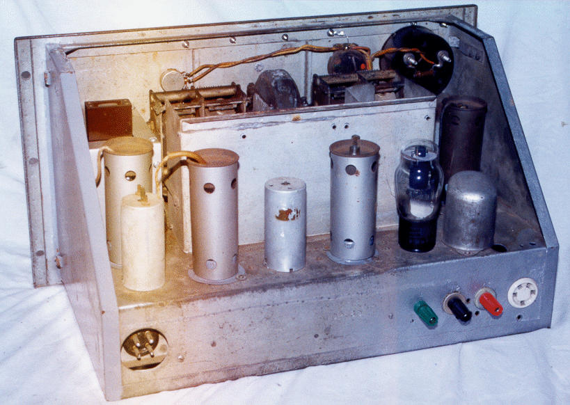
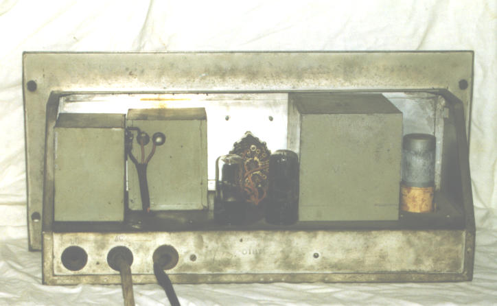
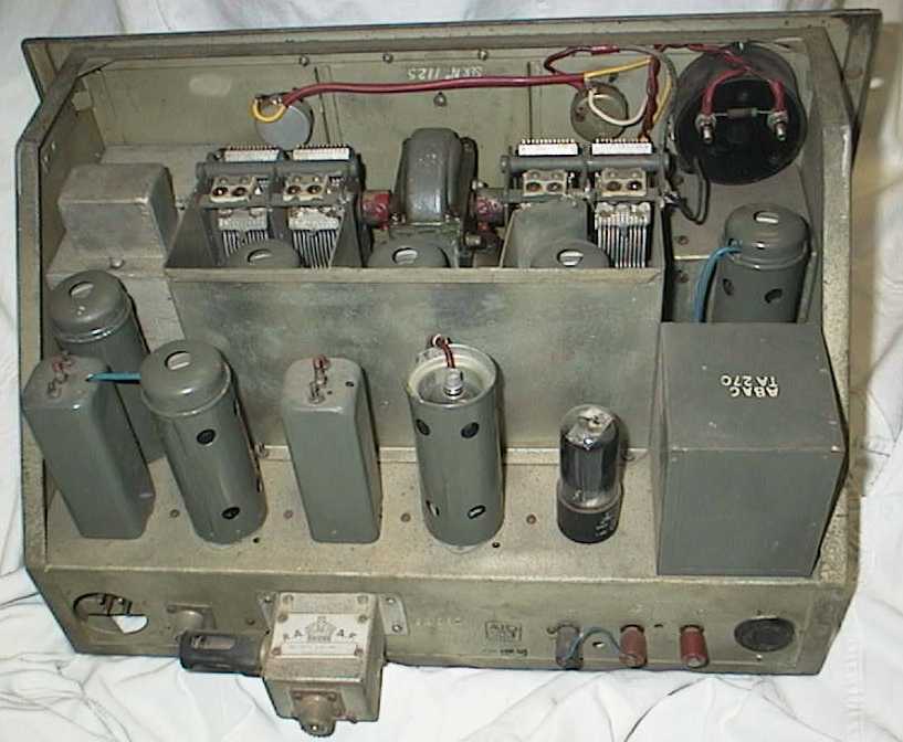
This is a rear view of the AR7 with the case removed. The chassis is made of 18 gauge sheet steel, copper, and cadmium plated, and spot welded. It is heavy. The left side recessed 4 pin male plug is the power input. The right side 5 pin socket is the speaker output. The speaker transformer shown is incorrect. It was a big square block, which also had a 600 ohm output for driving a line. The aerial could be a single wire or a balanced doublet, as there are 3 terminals on the back. These are plastic on this example. The photograph has a slight discolouration, probably due to light getting into the camera. I will have to rephotograph the inside.
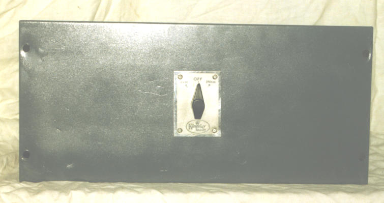
The power supply is a 19" rack mounting unit that has a switch on the front to select 240 VAC or 12 VDC operation, and a centre OFF position. The transformer has 2 primary windings, one for the 240v mains, and another for the 12v vibrator. It has two 6X5GT rectifiers, each with their plates tied together to serve as individual single diodes. There are several chokes in the power supply that are fibre bobbins wound with enameled wire. The paper label has fallen off the vibrator, and is shown sitting at its base.
RESTORATION
I have had this AR7 since I was 14 years old. It was my first communications receiver. I used to have a rack, speaker, and power supply for it, but they have disappeared, over the years due to moving house. I had to do extensive work to restore it to original condition, or as near as I could get it. The case has been repainted grey. The valve heaters had to be rewired from 6v to the original 12v, and all non original plastic wire, replaced with cotton covered wire. I had to find the original phone jacks, to replace a modern jack and a dial light. I made a cover for the crystal filter and rewired inside the crystal filter box. I replaced the RF gain, Selectivity, and AF gain control potentiometers as they were faulty. The valves had been replaced with metal valves so I returned these to the correct G types. I had to make bases for the valve shields, as these had been removed for the larger based metal valves. I then had to find the correct valve shields. The capacitors were mostly out of tolerance or leaky, so I replaced them all. I found 2 bad resistors and replaced those with the correct Body/Tip/Dot type, not modern colour coded striped resistors. There was a silicon rectifier under the space where the speaker transformer should be, and a mains power transformer. These were removed and a speaker transformer put there. I am still looking for the correct type. A new ceramic speaker 5 pin socket was fitted. The crystal was missing so a new one was fitted. I then did a complete alignment, and had a lot of trouble trying to get the crystal filter working properly. When I finally used a sweep generator, the alignment took 5 minutes, and was extremely accurate. This refurbishment took over 6 months.
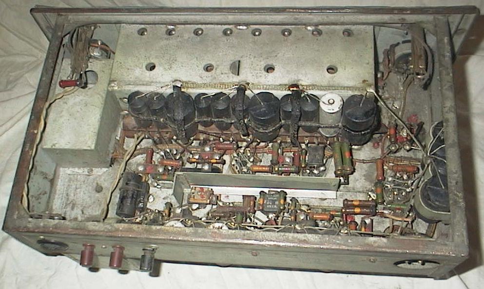
Most AR7 receivers have been modified. Here are photos of a rare example that still has all its original capacitors and resistors in place.
VARIATIONS
The AR7 was very popular with Ham radio operators and it is difficult to find one that has not been modified. Typical modifications were: changing the audio output transformer, bandspreading the coil boxes to the ham bands, replacing the RF and IF valves with miniature or metal valves, removing valve shields and valve shield base rings, replacing the phone jacks with ON/OFF switches and pilot lights. Other common modifications are adding a product detector for SSB reception, and building an internal power supply in place of the speaker transformer.
The DCA and RAAF had several modifications. The oscillator coil was removed from the coil box and a crystal was mounted in there. This crystal locked the receiver to one frequency. There was a modification, to allow remote control of the receiver, allowing the RF gain and BFO note to be operated from a remote position. This involved changing the S meter circuit so that it didn't use one half of the dual triode BFO valve, and it now became a reactance tube to control the BFO note. There was also a Squelch modification which involved adding a 6SN7 to an angle bracket and mounting this under the chassis. There was a minor audio output modification which only used one of the audio transformer windings. There was a modification to add a pilot light. There was a modification to change the AVC/BFO switch to a 3 position switch, which was AVC/none/BFO.
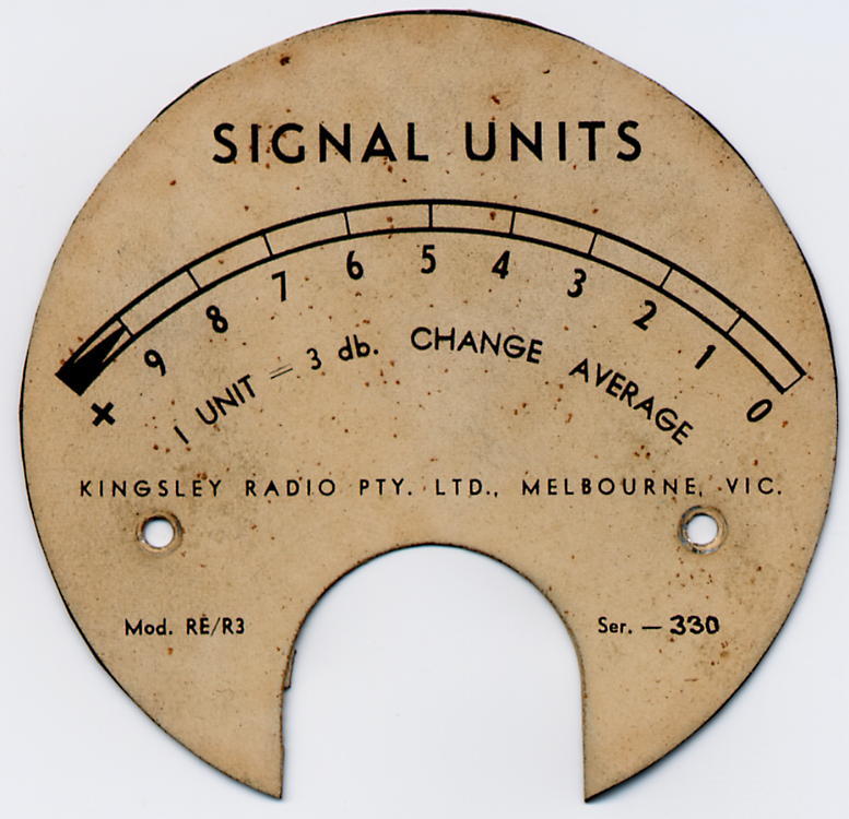
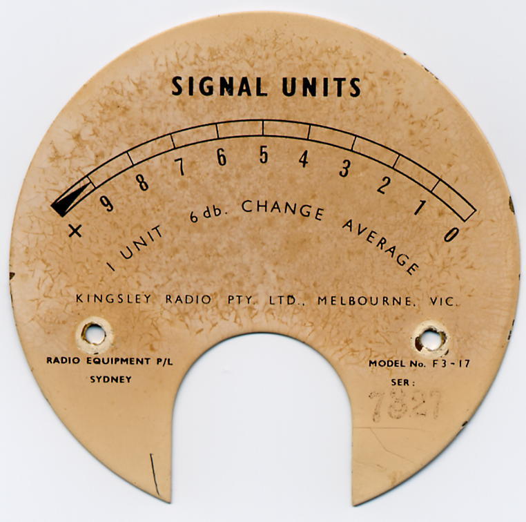
Production run variations included, round or square IF transformers, chassis and front panel bracing, different S meters (scales had 3 or 6 dB units, and meter pointers which were a red arrow head or black flat blade), and tropicalising.
Typically you will find an AR7 that will be incomplete, and will be missing: the crystal from the IF filter, crystal cover, and the nameplate. The rack, case, speaker panel, and power supply are not as common and are usually hard to find.
There was a late version with changes for TTY reception and it is labeled AR7A/1. The most obvious change is the change of the AVC/BFO switch to two toggle switches. This is so the AVC and BFO can be independently controlled. They also added a cathode follower to the back panel so that the mixer output signal can be connected to a Panadaptor. There is lead that is attached to a standoff near the mixer, that goes to the cathode follower. It is not connected directly to the mixer. There was a regulator added to the local oscillator to improve stability. The receiver can be connected to a Frequency Shift Keying Decoder, such as the AFSR-2, and used for Radio Teleprinter reception.
HISTORY
Howard Kingsley Love started the Kingsley Radio company in Melbourne, Victoria, in 1931. They manufactured domestic radios, and special orders, including diathermy machines. The R.A.A.F (Royal Australian Air Force) produced a specification for an Australian made high performance communications receiver. The Kingsley Radio company designed a receiver called the K/CR/11 and submitted it. It was adopted as the AR7. They placed an initial order for 20 receivers. The Army also adopted this receiver as the Reception Set No.1 and it had an engraved brass panel with a black background. I've seen AR7s with green panels. Another version was made for the Dutch Navy with a front panel in Dutch. There were more than 3200 receivers made.
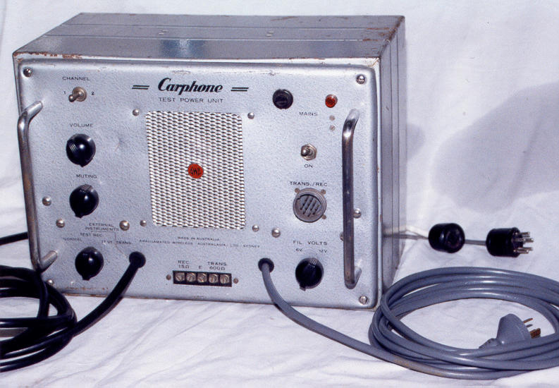
CARPHONE TEST POWER UNIT
A Carphone Test Power Unit made by A.W.A., is providing the power and the speaker. This is a different unit to the one that I have used to power my AR8 receiver. This one has two 5Y3 rectifiers in the circuit and 2 power transformers. When it is on Normal (or Receive) one is used providing 250v HT. When it is switched to transmit, the second one comes in and boosts the HT to 400v. The older model on the AR8 has one rectifier, and a dropping resistor, which is not as good a design as this unit.
REFERENCES
"When I think Back", Neville Williams, Electronics Australia, July/August 1994
"The Kingsley K/CR/11, (AR7)", Warick Woods, H.R.S.A. (Historical Radio
Society of Australia) Radio Waves, October 1997.
"Airways Radio Equipment Receiver Type A.R.7", Directorate of Airways, Department
of Civil Aviation, Melbourne, January 1947.
DIAGRAMS
Thanks to Peter May for the circuit and Parts list.
AR7 CIRCUIT
AR7 PARTS LIST
AR7 METER SCALE (3dB units)
AR7 METER SCALE (6dB units)
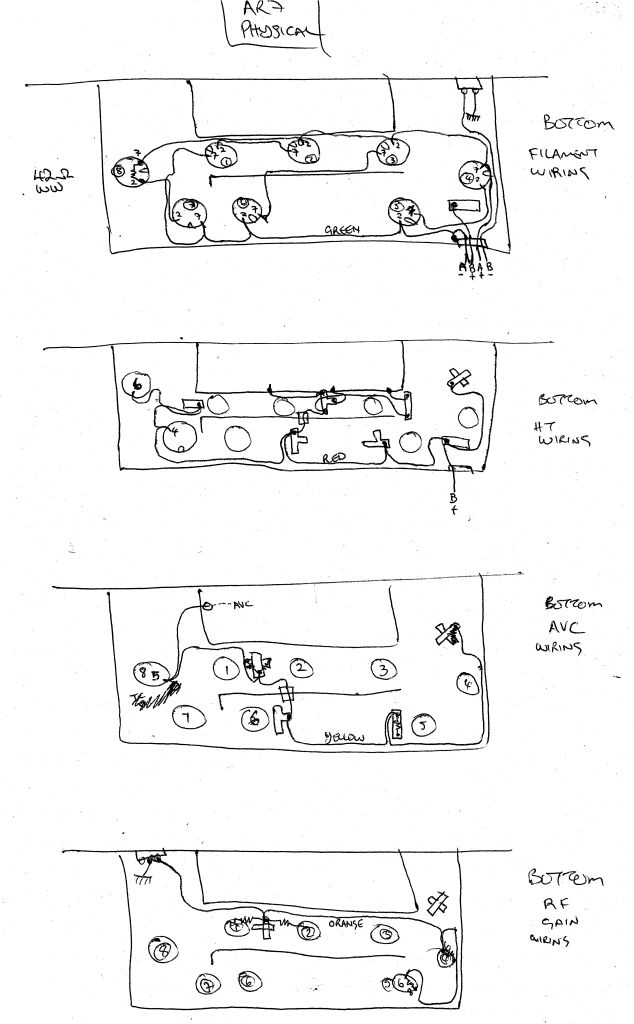
AR7 PHYSICAL WIRING SKETCH
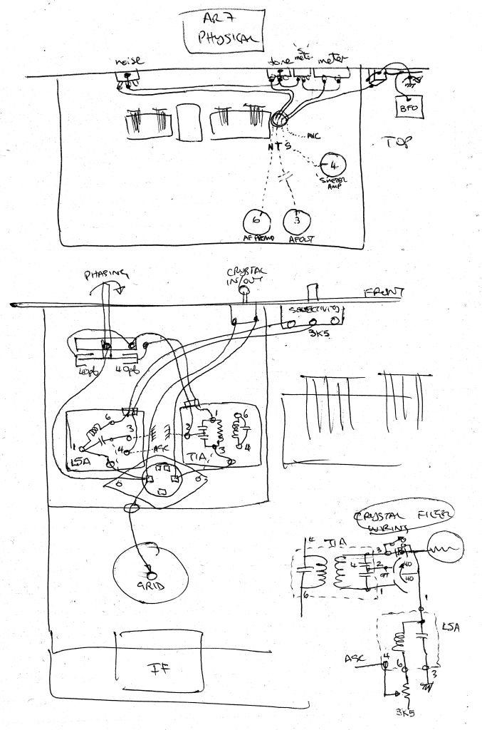
AR7 PHYSICAL WIRING SKETCH 2
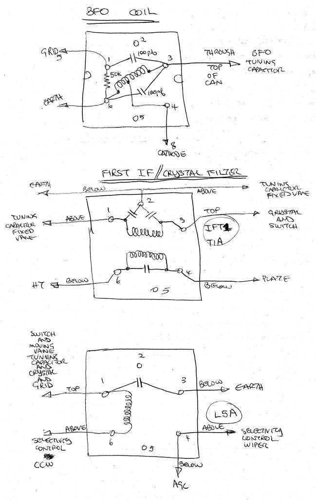
AR7 CRYSTAL FILTER WIRING SKETCH
AR7 CRYSTAL FILTER WIRING SKETCH 2
CARPHONE PSU circuit
LINKS
Military Radio Collection, AR7, Dave Prince
Written by:
Ray Robinson VK2ILV
Back to the INDEX (more radios)