ARB RECEIVER (CRV-46151)
The ARB receiver
is a US Navy aircraft receiver used in World War II. It covered the frequency
range 195 kcs to 9050 kcs in four bands. There is no gap in this frequency
coverage because it uses two IF frequencies of 135 kcs and 915 kcs. It is a 6 valve superheterodyne
receiver with a built in dynamotor power supply. It was designed to run off
28 volts DC with a normal current drain is about 2.4 amps but this will
rise to 4 amps when changing bands. It was made by RCA and also
known as a CRV-46151 and weighs 26.8 pounds with the CRV-10081 mounting
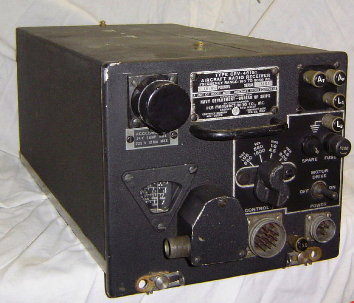
base. The radio
itself is a long deep box with a square front panel. The front panel controls
are minimal, as it was intended to be used as a remotely controlled receiver,
from a Pilot's or Navigator's control box. The BAND change is motorised,
the frequency tuning is by flexible Bowden cable, and the bandwidth and antenna
selection is by relay.
USE
The ARB was designed for the US Navy and was intended to be used with
the ATB transmitter, which was a similar size and produced 25 watts. The
ARB and ATB designs followed the previous ARV-50 and ATV-50 civilian aircraft
designs. About
30,000 ARB and about 4,000 ATB were made in the 1940s. The ARB/ATB were also
used in Australia by the R.A.A.F. The ARB was used in many aircraft, with
many other transmitters, and also in isolation as a general purpose receiver.
The receiver can use several types of antenna, and has four antenna terminals.
There are two terminals for a loop antenna, which are marked L1 and L2. The
L2 terminal can be used as an Earth terminal. There is one antenna terminal
which is marked AF for a fixed or short antenna, which means low capacity
or less than 180 pf. There is another antenna terminal which is marked AT
for a trailing or long wire antenna, which means high capacitance. Do not
connect an antenna or antennas to both terminals at once. If using 2 receivers
connected in parallel to the same antenna, use the AT terminal, regardless
of the antenna length. A loop and an antenna may be connected at the same
time, as an internal relay will switch between them.
The BANDs are:
Band Receive frequency IF frequency
Antenna
A 195 - 560 kcs
135 kcs
loop or extended
B 560 - 1600 kcs
135 kcs
loop or extended
C 1.6 - 4.5 mcs
915 kcs
extended
D 4.5 - 9.05 mcs
915 kcs
extended

CONTROLS
The ARB could be tuned and operated
from the front panel using a local tuning control knob and the BAND switch,
when the MOTOR DRIVE is switched OFF.
All local controls and connectors are on the front panel. The top left
hand corner has a connector (usually fitted with a protecting cap) that
provides 225 vdc at 12 ma and 28 vdc at 1 amp for any accessories.
There is a legend plate below this connector which displays the maximum
currents available. In the center at the top is the receiver nameplate,
above the handle. At the top right hand corner are the four antenna terminals.
Below the antenna terminals are two fuse holders. One is the main fuse for
the 28 volt DC supply (10 amps), and the other holds a spare fuse. Below
the fuses is the MOTOR DRIVE toggle switch, which turns OFF the band change
motor. This must be ON for remote control of the band change. In the centre
of the front panel is the BAND CHANGE switch, which will normally be operated
from the remote control box. It can be operated directly, but will only turn
in a clockwise direction, and should only be operated when the motor is turned
OFF. The knob is shaped so that it shows the band that is selected, and
the direction to turn it. At the lower left hand corner is a small triangular
tuning scale with a magnifying lens, and the gearbox for the tuning cable
entry. A bowden tuning cable is normally connected, but it can be removed
and a local knob fitted. At the bottom are two connectors. The 3 pin connector
is for 28 volt DC power input. The 16 pin connector is for the remote control.
An earth terminal is provided between the connectors. Also at the bottom
of the front panel are two snap slides, that lock the receiver into the
rack. No other
controls are available on the front panel, as they are all available on
the remote control box.
The ARB could be operated locally, but was usually operated
in the aircraft from 1 or 2 remote control boxes. The CRV-23254 was the
pilot's control box and the CRV-23256 was the navigator's control box.
This provided most functions except for the tuning, which relied on flexible
bowden cables and a CRV-23253 receiver tuning head.
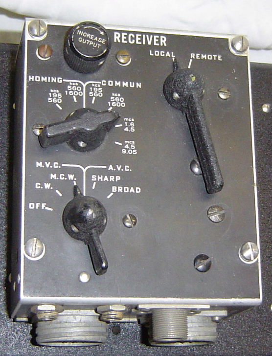
NAVIGATOR'S CONTROL BOX
The CRV-23256 Operators or Navigators
control box has two connectors. The left connector is normally connected
to the receiver. The box has a FUNCTION switch at the bottom. The first position
is OFF, which turns OFF the 28 volts DC to the ARB. In all other positions,
it is ON. The next two positions operate with manual volume or gain called
M.V.C. (Manual Volume Control). The first of these is for C.W. (Carrier Wave
or morse code) reception and turns on the BFO (Beat Frequency Oscillator).
The next position is the same, but with the BFO off, and is for normal M.C.W. (Modulated Carrier
Wave) or R/T (Radio Telephony or voice reception). The next two positions
on the switch use A.V.C. (Automatic Volume or gain Control) and they have
a SHARP or BROAD position. This changes the characteristic of the IF response
curve and is controlled by a relay in the receiver. Above the FUNCTION switch
is the BAND change switch. This selects one of the four frequency bands available.
The two lower frequency bands are selectable on the switch, called HOMING
(which uses the L1 and L2 loop terminals) or COMMUN (for communications)
which uses the normal AT and AF antenna terminals.
The BAND change switch and the FUNCTION switch are mechanically interlocked
with internal levers, so that the SHARP and BROAD positions are only available
on the three higher frequency bands. There is also mechanical interlocking
to ensure that M.V.C. is used when HOMING is selected. At the top is an
output control, labeled INCREASE OUTPUT, which is a triple ganged potentiometer.
One section is a manual RF gain control for the M.V.C. positions. The other
two sections are audio level controls for the A.V.C. positions. Each of the
two audio gangs are independent and one is for the low impedance audio output, and the other is for the
high impedance audio output. The big lever switch on
the right of the box, is the LOCAL/REMOTE selector. When in the LOCAL position,
all the controls work. When in the REMOTE position, the CRV-23254 Pilots box has all the working
controls, and a cable must be connected from the right connector, to the
pilot's control box. There is small screwed boss near the connectors, and
this can have a mechanical push/pull cable connected to it. When the LOCAL/REMOTE
switch is set to REMOTE, the cable is pushed, and a mechanical indicator
next to the Pilots control box, is activated, to show which mode it is in.
The box has two jacks to connect headphones.
PILOT'S CONTROL
BOX
The CRV-23254 Pilot's box is the same
as the left half of the Navigator's box, and has all same the working controls.
It looks like the Naviators box that has had the right half neatly swan off.
The only control missing, is the LOCAL/REMOTE switch. It has only one connector. This box also has two jacks to connect headphones.
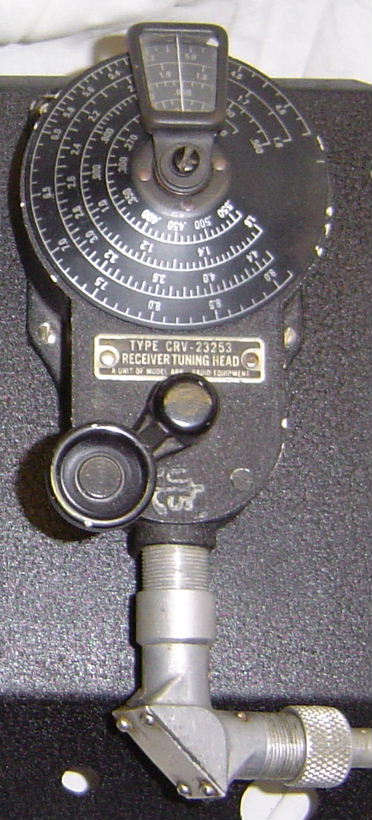
RECEIVER TUNING HEAD
There is a remote control tuning head type CRV-23253 which is a mechanical gear
box, with an indicating scale. It uses a flexible bowden cable to
tune the receiver. This was sometimes known as a "coffee grinder" because of the
winding action required. The indicating window can
be moved to the left or right hand sides, to allow for different mounting
positions in a cramped aircraft cockpit. This control is very similar to the
tuning head for the RU series of receivers, except they are calibrated in
degree graduations from 0 to 180, and not directly in frequency.
DESIGN
The radio has a long chassis with a central band change shaft traveling
the whole length. It has a knob on the front panel and a motor near the rear.
The motor can be remotely activated to turn the shaft and change bands, but
the shaft will only rotate in an anti-clockwise direction. The front panel
knob is shaped to allow local activation in only that direction, and also
to point to the band in use. The shaft passes through the antenna, RF, mixer,
and oscillator coil boxes, and also through the three IF transformers and
BFO coils. The valves are on the top of the chassis, along the right hand
side. Under the chassis is the wiring, the components, the dynamotor, and
the four gang tuning capacitor. The metal parts are all molded aluminium
sheet metal, and many components are located inside the coil boxes. The audio
transformer and choke are in one sealed unit. The larger assemblies are modular
and can be easily changed.
The first valve is an RF amplifier (12SF7). The antenna coil
primary, has circuitry to compensate for the different antennas, and a relay
to switch in the loop on the two lower bands, when the BAND switch is set
to HOMING. There is also a neon tube which will conduct when any high voltage
appears on the input, and will protect the antenna coils. The grid of this
valve (and also
the first IF valve) is connected to the AVC voltage, which comes into action
when AVC is selected. The
cathode of this valve (and also the first IF valve) is connected to the
RF gain control, which comes into action when MVC is selected. The output from the plate
of the RF amplifier is unusual, in that it goes through two tuned circuits,
before reaching the grid of the mixer valve (called the detector or converter
in the manual). The mixer is a 12SA7 valve, with its plate circuit connected
to either of two IF transformers of different frequency, selected by the
BAND switch. The oscillator is an electron coupled type (Hartley), and so
only requires a tapped coil. The oscillator is on the low frequency side
for the lowest BAND, but on the high side for the other three higher BANDS.
The oscillator has a regulated plate voltage to improve frequency stability,
using a small neon tube. The first IF amplifier is also a 12SF7 valve, with
RF gain or AVC applied, depending on the MVC/AVC switch. The plate of this
valve goes through the next dual IF transformer to the second IF amplifier
which uses another 12SF7 valve. The plate circuit of this valve goes through
the third IF transformer, to the single diode in this same valve, which
is used as the audio detector. The audio is then capacitively coupled directly
to a 12A6 audio output amplifier. There is no audio pre-amplifier
stage, or volume control. The audio output amplifier
has negative feedback and cathode bias. The plate circuit is connected to
an audio output transformer, and this has two output windings, to give a
low impedance of 600 ohms for headphones, or a high impedance of 8000 ohms.
These are selected by jumpers in the control box, and this is where the audio
volume control is located. The BFO (Beat Frequency Oscillator) which is used
on CW signals, consists of a further 12SF7 valve, also connected as an an electron coupled type
(Hartley) oscillator,
but with two coils so that it can beat with the IF frequency selected. The
frequency is selected by the BAND switch. The BFO is turned OFF by removing
the high voltage, by shorting it to earth through a resistor. The diode in
the BFO valve is used as the AVC detector.
This radio looks like any normal superheterodyne, but on close examination,
it shows that is contains many subtle design features. The selection of the
three different types of antenna with appropriate matching and high voltage
protection. The loop antenna being selected by a relay. There is extra coupling
across the antenna coil to ensure increased coupling at higher frequencies,
and thus uniform gain across the band. The cascaded dual tuned RF coils
between the RF amplifier and the mixer, which are arranged for under-coupling
at the low end of the band and over-coupling at the high end. The mixer oscillator
has a regulated high voltage supply for frequency stability. There are dual
frequency IF transformers so there is no gap in the frequency coverage,
and these are automatically selected. There are de-coupling rings fitted
between the IF transformer windings to control the coupling and produce deliberate
under-coupling. In addition, the first two IF transformers have an extra
winding which is switched in by a relay to change the bandwidth from SHARP
to BROAD. The second IF amplifier valve has two cathode resistors and both are switched in
to provide a lower stage gain for CW reception. The third IF transformer
is over-coupled and is permanently in circuit and not switched out by the
BAND switch. The audio output valve has negative feedback to control
the audio frequency response. There are two audio output impedance's available.
The BFO oscillates at half the IF frequency, to avoid pulling by the received
signal. The second harmonic is used. There is no BFO pitch control, as the
BFO is fixed for a 1khz beat note. There are mechanical interlocks in the
control boxes, to ensure that correct combinations of settings always occur.
RESTORATION
The ARB was in a very good and clean condition when I got it, but
had been modified a little. Luckily there are no holes
drilled in it. I rewired the valve heaters to the original 24 volt, as they
had been modified for 12 volts. I removed the added speaker transformer,
and reconnected the original one. There were some disconnected wires around
the front connectors, homing relay and bandwidth relay, and I was not sure
what they did, so I traced out the circuit and reconnected them. The main connector was hanging
out the front, so I bolted it back into place, reconnected the wires and
laced the form into a neat bundle. I added the missing power connector. The front mounted
gearbox for the bowden cable was missing its cover and the bevel gear,
so I replaced it with one from my junk box. I fitted a local tuning knob,
and it seems to manually tune properly. The dynamotor was
missing, but luckily I found the correct one in my box of dynos. I greased
the bearings and checked the brushes, and it powered up and generated the
correct HT voltage. I then made a mounting plate for the dynamotor, so that
it fits underneath and inside the ARB. That finished the mechanical work.
I located the correct connectors in the junk box, and made up a power
cable and a remote control cable. There is a power switch on the remote
control box, so you need this box, or you need to bridge 2 pins on the remote
control connector. I connected up a control box and then applied 28
volts DC. It gave me a fright as the dyno span up, and the band change motor
burst into life. The band change motor stopped at the selected band, and
the dyno settled down to a hum. I tried the switches. The band change motor
works, and changes bands nicely, and rotates the front band change
knob, whirrrr....clunk. The homing relay works fine. The SHARP/BROAD bandwidth
relay was not working. I checked it and the coil was open circuit. I replaced
the coil with a spare, and it works fine now. So all the electro-mechanical
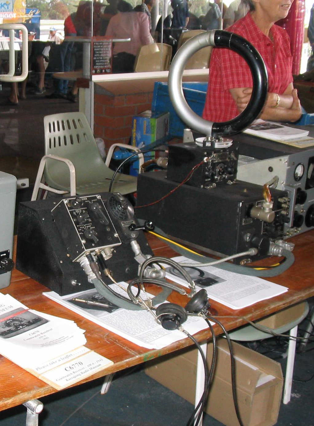
parts work, now on to the electronics. The photograph shows the ARB under
test.
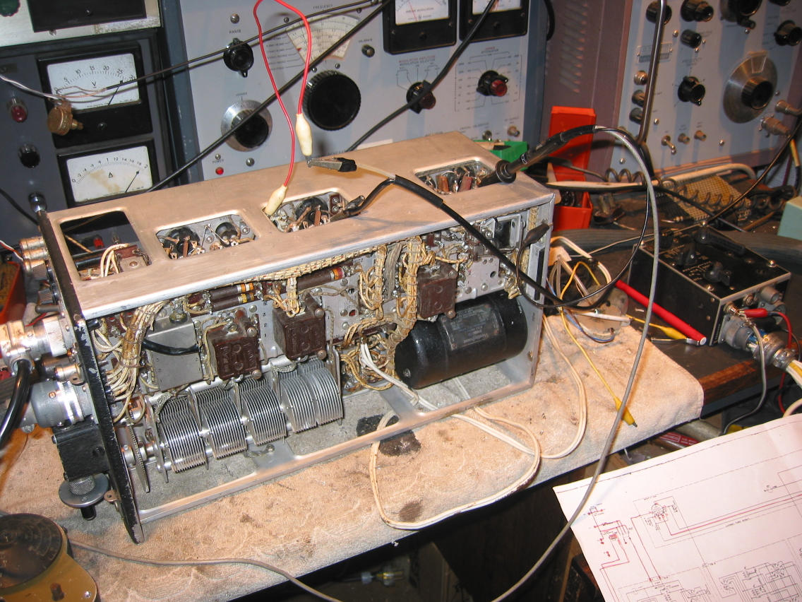
I plugged
a speaker into the headphones jack, but no sound. The speaker transformer
was open circuit. Since it is a sealed box complete with a choke, I needed
to find a new one. So I hooked up a temporary transformer. The photograph
shows white wires connected between the dyno and the tuning capacitor. The
speaker transformer is lying on the bench next to the control box, at the
right. I heard signals and noise but the stations were distorted and the sensitivity low.
I checked the voltages on the bases of the valves. I discovered an open
circuit resistor in the screen of the mixer and replaced it with one
of a similar looking type. The screen volts were now correct and the voltage
regulator was glowing, but no change to sensitivity or distortion! All the voltages were
found to be right, so it wasn't that. I looked at the audio signal with
a CRO and noticed that IF frequencies were being applied to the audio amplifier!
This meant the detector was malfunctioning. I had to open the CW/IF can
and look inside, and there I found an open circuit resistor in the diode
load. This cured the audio distortion and the audio was now clean and loud.
I began a 135kcs
IF alignment and noticed that one of the IF transformers would not tune
at all. I opened
the 2nd IF can and found a broken wire near the SHARP/BROAD bandwidth relay.
The IF tunes fine now. Alignment of IF completed satisfactorily, and the
IF sensitivity was good. I changed bands to use the second IF frequency
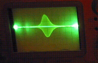
of 915 kcs and aligned it as well. I connected the sweep generator, and
displayed the bandwidth of the IF and activated the SHARP/BROAD control.
The relay snapped in, and the bandwidth broadened out nicely. I aligned the
oscillator and RF coils with no problems. The receiver was working nicely.
The photograph is of the IF bandpass.
I made up
a 28 volt DC supply and mounted it in a case. On the front of the case I
mounted the Navigator's control box and the tuning head. Inside the box
and behind the controls is a speaker. This setup was on display at the Central
Coast Field day on 29th February 2004.
OPERATION
The ARB receiver is easy to use, despite the small frequency window on
the front panel, and the flexible tuning shaft. If there are no sharp bends
in the flexible cable, the tuning is smooth with no backlash. The fixed BFO is
not a problem as SSB can be resolved easily. The combined gain control works
well for both RF gain and audio gain. The remote control of the loop antenna
selection and the bandwidth is nice. The remote control of the BAND is a
delight! It is very satisfying to watch the motor change bands. The sensitivity
is good, and audio output very good. It is a pleasure to use.
ACCESSORIES
The accessories connector should be normally covered with a cap, to prevent
contact with the 250 volts DC, and shorting of the 28 volts DC. There are
two studs on the top of the ARB that allow a homing receiver of type ARR-1
or ZB-2 to snap on. This homing adapter uses the ARB power from the accessories
connector and provides output to the antenna input. Another accessory that
can be used is an LM series frequency meter, which can be used to align or check
the frequency accuracy of the ARB. A passive loop would normally
be connected to the L1 and L2 terminals, but a DU-1 loop amplifier can
also be powered from the accessories connector.
REFERENCES
Aircraft Radio Receiver Model ARB, R.A.A.F. Pub. No. 405 Chap V.
Aircraft
Radio Transmitter Model ATB, R.A.A.F. Pub. No. 404 Chap VI.
CIRCUIT simplified (53 kB)
CIRCUIT normal (112 kB)
CIRCUIT big (660 kB)
CIRCUIT big (739 kB)
WIRING DIAGRAM (94 kB)
LAYOUT (top)
LAYOUT (bottom)
copyright
by:
Ray Robinson VK2ILV
Back to the INDEX (more radios)