BC-223 TRANSMITTER
INTRODUCTION
The BC-223 is an HF communications transmitter, designed at Fort Monmouth,
and made in the USA in 1940, by the RAULAND CORPORATION.
When combined with the BC-312 receiver, it becomes the SCR-245 radio station.
The transmitter covers the frequency range 2.00 to 5.25 mHz and provides CW
(Continuous Wave), MCW (Modulated Continuous Wave) and AM (Amplitude Modulation).
It can produce a nominal 10 watts into a whip antenna. The transmitter has five valves,
two VT-62 triodes, and three VT-63 tetrodes. It was intended as a portable transmitter
or for installation in jeeps, scout cars, trucks, half tracks, light or medium tanks,
and normally mounted on an FT-173 shock mount, with an optional FT-172 top steady
(the top of the case has the 4 holes pre-drilled). The power supply can be 12 or 24 volts DC.
It weighs 26 pounds, each coil box is 9 pounds, and the power supply weighs 33 pounds.
The frequency coverage of the transmitter is divided into 3 bands,
and each band has its own plug in coil box. They are:
TU-17-A 2000-3000 kHz
TU-18-A 3000-4500 kHz
TU-25-A 3500-5200 kHz
The coil boxes, when not in use, are housed in a CS-56 protective metal box.
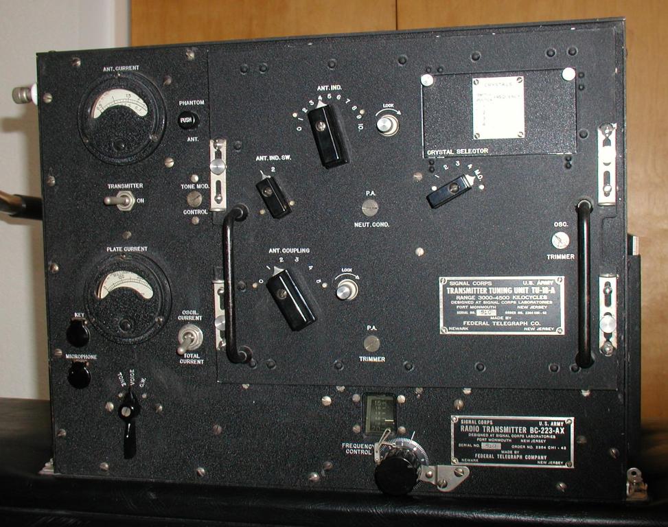
Figure 1: BC-223 TRANSMITTER
CONTROLS
The controls are very simple. There are 2 meters on the left hand side,
one for ANTENNA CURRENT (0-3 Amps), and one for PLATE CURRENT (0-300 mA).
Between these is a toggle switch to turn the transmitter ON and OFF.
Under this is a 3 position rotary switch to set the mode, TONE (MCW), VOICE (AM), and CW.
There are 2 jacks at the lower left hand side with snap covers. One is labeled KEY
and is for a J-45 morse key. The other is labeled MICROPHONE, and is intended for
a T-17 hand held microphone or a T-30-A throat microphone. When used with the BC-312 receiver,
these jacks are not necessary, as they are duplicated on the receiver.
There is a spring loaded push button to allow an internal PHANTOM Antenna to be switched
in as a tuning aid. There is a screw out blank cover that allows the TONE level to be set.
Below this is spring loaded toggle switch, to allow the Plate Current meter to
read the oscillator current. At the bottom in the middle is the tuning control,
which is labeled FREQUENCY CONTROL and has a mechanical lock.
This is graduated in divisions from 0 to 100, and there are 3 tuning charts in a
pocket on the right hand side of the case, that give approximate settings for the
frequency in use. This tunes the oscillator and power amplifier. For crystal operation,
use this control to dip the Plate Current.
Each plug in coil box has several controls. At the top left hand corner is the
Antenna Inductance control, labeled ANT. IND. and graduated 0 to 10 (it has a locking device).
Below this is the Antenna Inductance switch, labeled ANT. IND. SW. and has 2 (or 3) positions.
There is also an antenna coupling control labeled ANT. COUPLING and graduated 1 to 5
(it has a locking device). These are used to match the antenna at the desired operating frequency.
On the right hand side is a little door that protects 4 crystals in sockets.
Below this is a switch to select MO (Master Oscillator), or the 4 separate crystals.
There are also 3 controls protected by screw out plugs. These are for neutralisation,
oscillator calibration, and PA tracking.
The transmitter has two large 9 pin connectors on the left hand side,
one is for the dynamotor supply (DYNAMOTOR), the other connector is for the remote control
(CONTROL), which is usually provided by the BC-312 receiver. The use of this connector is optional.
There are also several binding posts. One is for the antenna (ANT.) and another is for the
counterpoise (CPSE.). There is also a ground (GND.) and 2 receiver binding posts (labeled REC.),
which connect the antenna to the receiver, when not transmitting. One of these is
a shielded binding post. The counterpoise and ground binding posts are often joined together.
PRESET ADJUSTMENTS
There are 4 adjustments that are preset, and are concealed behind screw out plugs.
These only need to be set occasionally, for calibration, and after service.
To set the TONE LEVEL, the potentiometer is adjusted so that 0.6 volts AC appears
across pins 46 and 53 on the CONTROL connector. This affects the MCW modulation level.
An alternate method using modern equipment, is to employ an oscilloscope,
and adjust for the correct voltage.
To NEUTRALISE the transmitter, the procedure in the manual uses a 200 mA RF ammeter
in series with the antenna, and if the plate current meter is not held or locked in the OSCIL.
position, it can be burned out. Adjust the PA NEUT. COND. control for minimum RF antenna current.
This is done for each plug in coil unit. An alternate method using modern equipment,
is to employ an oscilloscope, and adjust for the smallest waveform amplitude.
To CALIBRATE the oscillator, set the FREQUENCY CONTROL to a setting from the chart
and verify with a BC-221 frequency meter. If it is different by more than 3 kHz,
adjust with the OSC. TRIMMER capacitor. This is done for each plug in coil unit.
An alternate method using modern equipment, is to employ a frequency counter,
and adjust for the correct frequency.
To ensure the PA (Power Amplifier) tuning TRACKS the oscillator frequency,
set the controls to CW with no antenna connected, and key the transmitter.
Tune FREQUENCY CONTROL through its full range. The plate current should not
change by more than 10 mA. If it does, adjust the PA. TIMMER capacitor for minimum
current at 3000 kHz, 4500 kHz, and 5250 kHz (depending on the coil box in use).
The plate current is normally 60 to 70 mA.
TUNING PROCEDURES
The manual provides a tuning sequence, but has no explanation of what the controls actually do.
MO OPERATION
Set the FREQUENCY CONTROL to the value indicated on the chart (for the coil box in use).
Key the transmitter.
Check with a frequency meter.
CRYSTAL OPERATION
Key the transmitter.
Hold the meter switch in the OSCILL. CURRENT position
Adjust the FREQUENCY CONTROL for a dip in the meter reading.
If the dip is asymmetrical, tune slightly to the broader side.
ANTENNA TUNING
Set the ANT. COUPLING control near 1.
Key the transmitter.
Increase ANT. COUPLING and the ANT. IND. control until maximum antenna current is shown.
If the antenna does not tune to resonance, use position 2 of the ANT. IND. SW. to achieve resonance
Increase ANT. COUPLING and ANT. IND. until plate current is 120 mA for maximum antenna current (CW)
Lock controls.
TONE OPERATION
Key the transmitter.
Tune the antenna.
Set the plate current to less than 250 mA (MCW)
VOICE OPERATION
Key the transmitter.
Tune the antenna.
The antenna current should increase when speaking, but not exceed 260 mA (VOICE)
If there is downward movement, decrease the ANT. COUPLING.
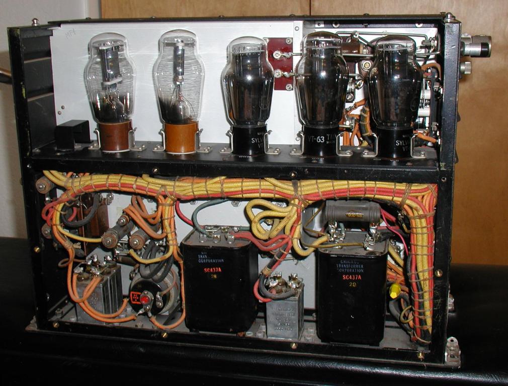
Figure 2: BC-223 REAR VIEW (covers removed)
DESIGN
The transmitter is in a vertical steel case, with the coil units plugging into the front.
The mechanical design looks solid and rugged. All of the frequency determining components
are in the coil boxes, including 4 crystals in FT-171-B sockets. There is a ventilated
access panel at the back that reveals a horizontal shelf supporting the 5 valves.
The oscillator is a valve type VT-62 (or 801), which can be crystal controlled, or
used as a MO (Master Oscillator), which is a tunable oscillator. It is not calibrated
in frequency, but with a 0-100 scale, so that a chart has to be used to set the frequency.
Net operation may be a problem, so the manual recommends using a BC-221 frequency meter.
The oscillator drives a VT-62 (or 801) power amplifier. The plate is fed by an RF (Radio
Frequency) choke, and it is capacitor coupled to the matching network.
The FREQUENCY CONTROL tunes the tank coil, and it is ganged to the oscillator tuning.
This is actually a 7 gang capacitor, located across the front of the transmitter.
Four gangs are for the oscillator, and each coil box connects them in parallel,
depending on how many it needs. Three gangs are for the PA and are also connected
in parallel, depending on the coil box. It has a trimming capacitor and a tracking
compensating coil. The tank has a variable coupling control (ANT. COUPLING)
and the manual warns about coupling, suggesting that more power is obtained
by not overcoupling. The coupling coil, then goes to a switchable series inductance
(ANT. IND. SW.), and a variometer (ANT. IND.) providing variable inductance,
to enable the electrically short whip antennal to be matched for maximum antenna current.
The coupling coil bottom end is connected to an external binding post (CPSE.) so that
it can be connected to a counterpoise or to ground (the steel case).
There is an internal PHANTOM antenna which consist of a 107 pF capacitor and a 6.4 ohm
series resistor, to enable pre-tuning. This is activated by pressing a spring loaded button.
The modulator uses a pair of VT-63 (or 46) tetrodes (triode connected, grid and screen grid)
in Class B being driven by another VT-63 (or 46) speech amplifier (also triode connected,
but screen grid and plate). There is a microphone transformer, an interstage driver transformer,
and high level modulation transformer for AM plate modulation.
It is intended for a carbon microphone. There is an Interrupter
BZ-7 (part 34) a simple buzzer, with an RC (Resistance Capacitance)
filter to smooth the output, which then feeds into the microphone transformer.
It has a preset level control (TONE MOD. CONTROL). This is for MCW operation.
There are 2 resistors in the negative HT (High Tension) line, that supplies bias
for the PA and the modulator valves. It is set up to save power, so when in the VOICE mode,
the transmitter is cold. When pressing the PTT (Press To Talk) button on the microphone,
the dynamotor spins up, the valves heat up, and it takes 3 seconds, before you are transmitting.
This will also prolong valve life, in the event that there is vehicle vibration.
When in TONE or CW modes, the filaments are powered up, the dynamotor is providing 500 volts,
and the keying relay is used to remove the back bias from a 25K resistor in the HT negative line.
The two RF valves have 7.5 volt filaments, so they are connected in parallel,
and are directly heated. The three modulator valves have 2.5 volt indirectly
heated cathodes so they are connected in series, so that they add up to 7.5 volts.
The power supply has to be adjusted to deliver 8.2 volts for the valves, to allow for cable losses.
The carbon microphone is powered from the filament string, from the 5 volt point in the modulator
filament string, which seems a little odd, as plugging in a microphone will unbalance
the filament currents slightly. The 12/24 volt switch in the transmitter (part 30-2)
switches in 2 resistors (part 46 and part 47) to drop the voltage for the antenna changeover
relay (part 33).
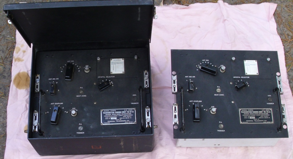
Fig 3: BC-223 COIL BOXES
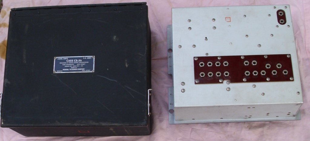
Fig 4: CS-56 COIL CASE AND COIL BOX REAR
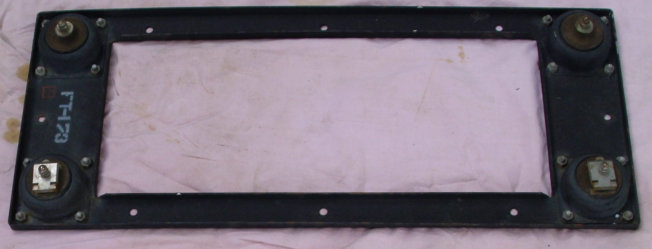
Fig 5: FT-173 SHOCK MOUNT
POWERSUPPLY
There are three power supplies that can be used. The vibrator supply is a PE-125-AX
and can run from 12 or 24 volts DC. The dynamotor supply is a PE-135-AX and can run
from 12 or 24 volts DC using a DM-49-AX dynamotor. The older dynamotor supply is a PE-55
and is 12 volts DC only, and uses a DM-19 dynamotor. These power supplies provide 500 volts
DC at 250 mA. They also supply 8.2 volts for the valve filaments. The supplies draw 14 Amps
for CW and 19 Amps for MCW/AM at 12 volts (8 and 10 Amps respectively for 24 volt operation).
The vibrator supply is essentially 2 supplies in parallel. It has two VB-5 vibrators,
two transformers, and two VT-249 (or 1006) valves. The valve outputs are then connected together,
and go through an HT filter to the transmitter. It also has a start relay, that allows
remote operation. The dynamotor power supply is a simple supply with filtering and fuses.
It has a start relay, that allows remote operation. The PE-55 circuit is essentially
the same as the PE-135 circuit, but without the 12/24 volt links. The PTT relay has
a 35 ohm resistor linked in, for 24 volt operation of the coil. The dynamotor has two
12 volt windings, that are in parallel for 12 volt operation, or that are in series for
24 volt operation. The PE-55 dynamotor only has a single 12 volt winding. There is a
2 ohm filament adjusting resistor for 12 volt operation, and another resistor (0.75 ohms)
is linked in, for 24 volt operation. Of interest, there is a 10 ohm resistor that is
switched across the dynamotor primary, when the PTT is released, this will slow the dynamotor.
The transmitter needs a 7.5 volt filament supply, so the voltage needs to be set to 8.2 volts
with the FIL VOLT ADJUST resistor.
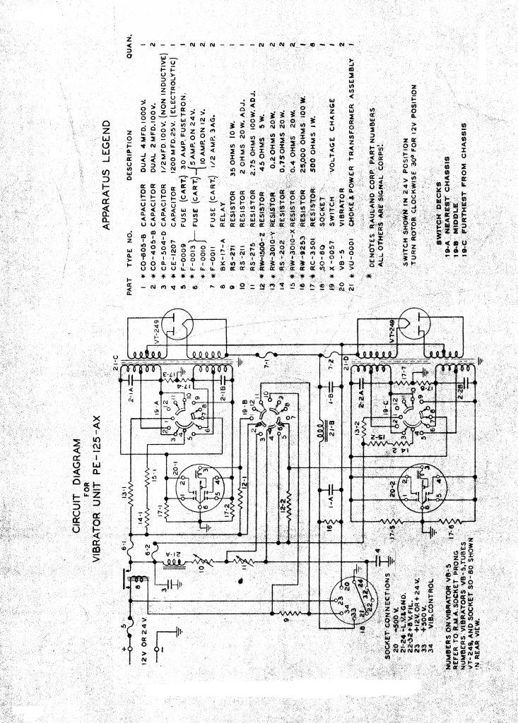
Fig 6: PE-125 VIBRATOR POWER SUPPLY CIRCUIT
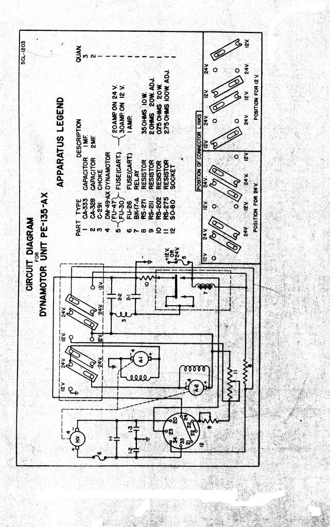
Fig 7: PE-135 DYNAMOTOR POWER SUPPLY CIRCUIT
RESTORATION
The transmitter required no restoration as it was almost new. I reversed one modification,
as it had a minor wiring change to allow the muting of a receiver. The previous owner
supplied the information as he had kept the details, so reversal was easy.
The large 9 pin plugs had to be found, and then the cables made up.
The plugs are the typical pre-war US Navy type, with the press button lock, PL-149 and PL-150.
I used heavy duty 8 core cable, and wired it as shown in the manual.

Fig 8: CABLES AND PLUGS
The power supply came from a different source than the transmitter.
It was the older dynamotor supply, and only has a brief mention in the manual,
and no circuit was provided. It required cleaning and repainting.
The dynamotor was greased and the brushes checked. The 12 volt input had one
of the bolts broken off, so this was replaced. The input cable clamps were rusty
so they were cleaned and passivated. The internal components were all under covers,
so they were clean, and only needed testing. The circuit was inspected,
and as this supply was for 12 volt operation, only, there were no links to configure.
The supply was powered up and checked. The capacitors did not need reforming,
and the 500 volt output was steady. The supply was connected to the transmitter,
and the BC-223 internal voltage switch was set to 12 volts. The FIL VOLT ADJUST
resistor in the power supply was adjusted to 8.2 volts under load.
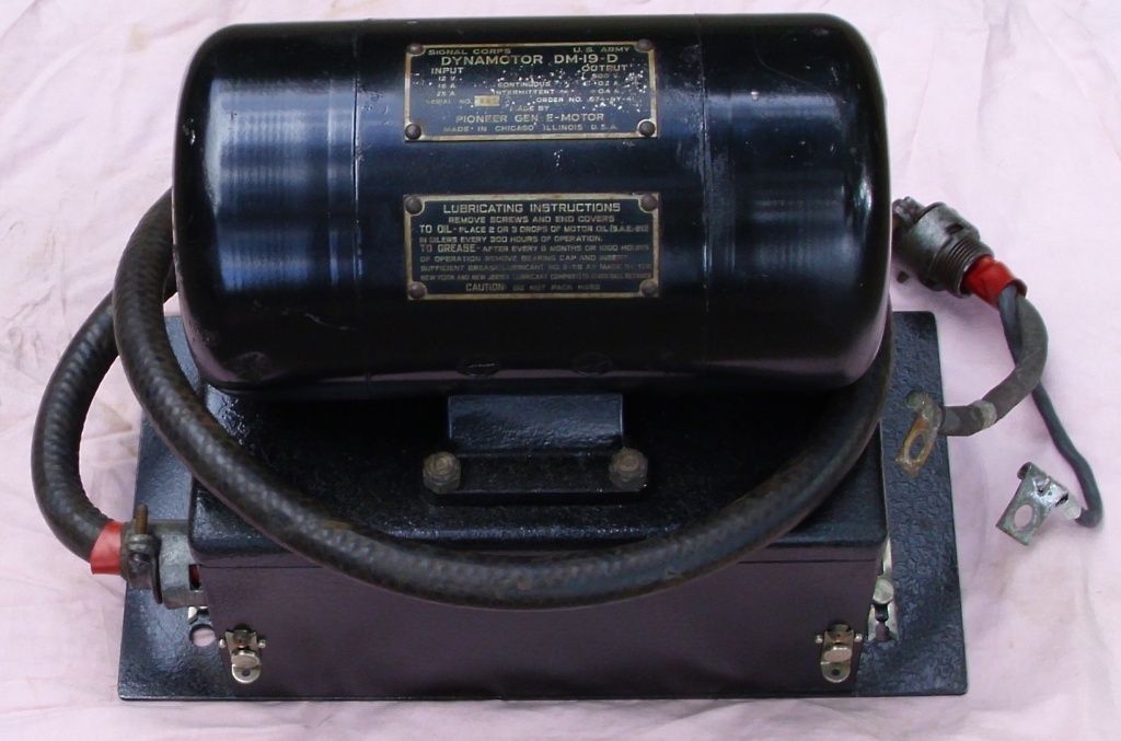
Fig 9: PE-55 POWER SUPPLY
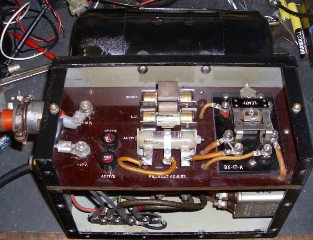
Fig 10: PE-55 POWER SUPPLY INSIDE
OPERATION
The BC-223 transmitter is intended to be set up, adjusted, tuned, then used on one frequency only.
All the operation is supposed to be done from the receiver. This why it has locks for the controls,
and remote control facilities. The locks also help when used in a vehicle so that vibration
does not affect the adjustments. In the VOICE mode, you often miss the first 2 words of
a transmission, when you forget that the dynamotor has to spin up and the valves have to heat.
The manual says Before talking into the microphone, wait about 3 seconds to allow the tubes
to warm up. When actually operating the transmitter, you can watch the PLATE current
rise (after about 2 seconds), then watch it fall back a little when the modulator starts
drawing current. This is a practical way of knowing when the modulator is ready.
I used a digital storage oscilloscope, to graph the valve warm up times.
The graph shows 3 traces, channel 1 is the HT (in PURPLE), channel 2 is the Oscillator
(in GREEN), channel 3 is the modulator (in YELLOW). The horizontal scale is in 1 second
increments. The vertical scale is in 100 volt increments. Four seconds from the left is
a 100 volt spike, when the PTT relay is activated. The HT begins to rise, and reaches 400
volts in 1.5 seconds. The oscillator valve heats and begins to draw current after 1 second,
then breaks into oscillation at 1.5 seconds. There is a purple and white dashed cursor
marking this point. The modulator begins drawing current at 4 seconds, and is fully conducting
at 7 seconds. There is another cursor at the 5 second mark. The graph shows the PTT being
released at 10 seconds. The curves indicate that waiting 5 seconds before talking is more realistic.
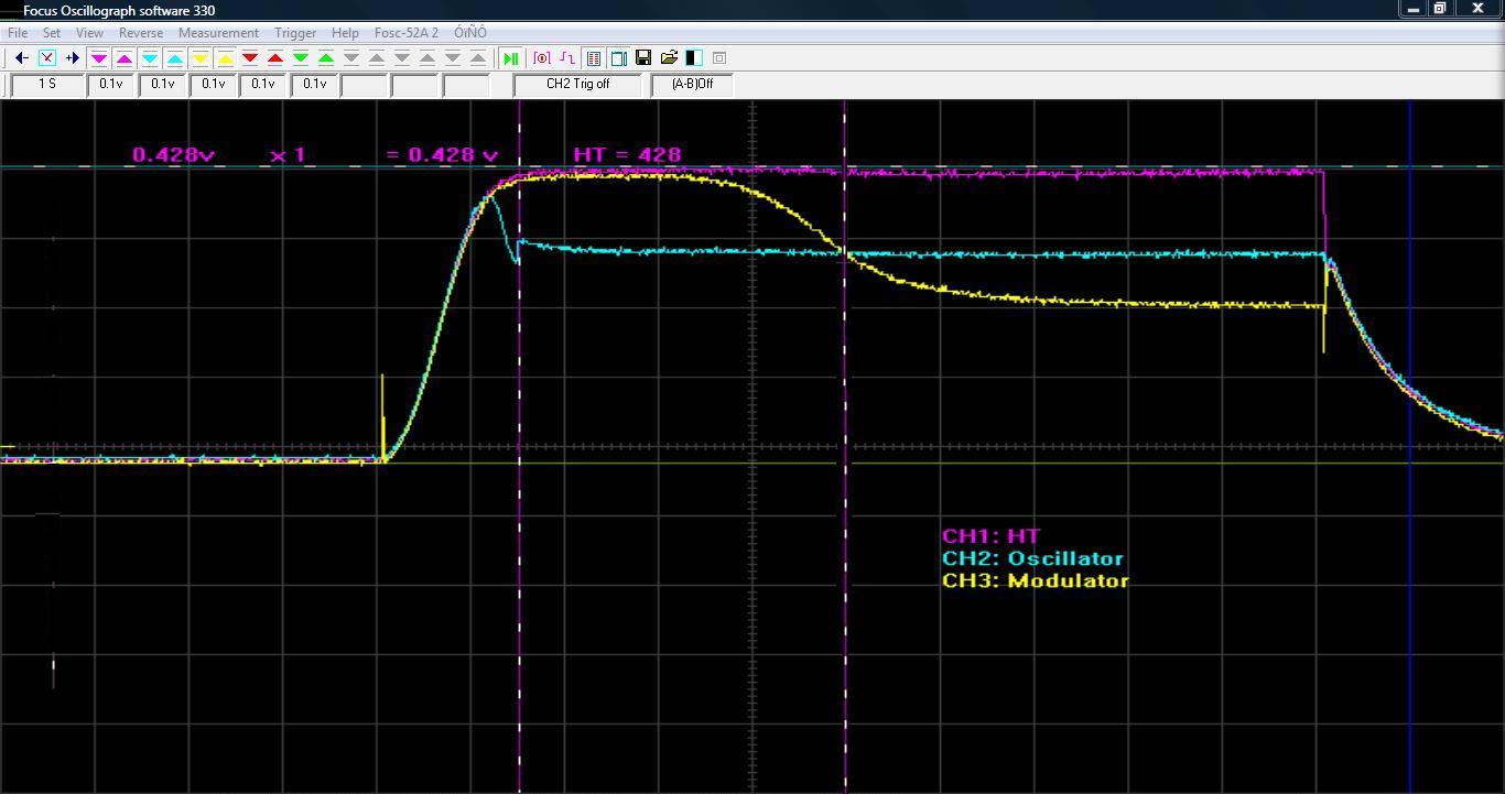
Fig 11: BC-223 VALVE WARM UP GRAPH
CONCLUSION
I was very lucky to find this example, as the previous owner had purchased it as new.
I am the second owner. It was made by the FEDERAL TELEGRAPH COMPANY in 1942 and was
never issued. The transmitter has the serial number 910, and the 3 coil boxes also
have the same serial number. The circuit in the manual is a little hard to read,
and so it is not clear sometimes, what the controls do. The manual is partly an
INSTALATION manual, an OPERATORS manual, but not a very good WORKSHOP manual.
It supplies the BC-312 receiver circuits as well as several installation and cabling diagrams.
The transmitter is nicely built, and the design straight forward. I wonder at the use 7.5 volt
and 2.5 volt filament valves. A better choice would have been 6 volt or 12 volt valves.
The transmitter is easy to use, and the controls easy to operate, with the exception of
the stiff PHANTOM ANT. push button, and the OSCIL. current meter switch. I can see why
they are spring loaded, but they are very stiff. The antenna matcher tunes a whip antenna
very easily. It is nice to watch the bright emitter valves light up.
I was worried the first time I keyed the transmitter and this happened.
I thought I had the wrong voltage on them, and had burnt them out!
It is a lovely transmitter to use.
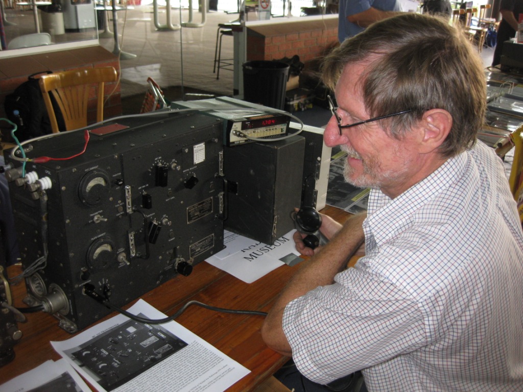
Fig 12: BC-223 IN USE AT THE WYONG FIELD DAY, FEBRUARY 2011
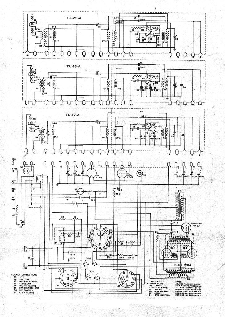
Fig 13: BC-223 CIRCUIT
REFERENCES
Instruction Book for Radio Set SCR-245
Copyright:
Ray Robinson VK2NO
INDEX