
Figure 1: Sealed Package
During a restoration of a PRC-64 transceiver, a power source was required, so a replacement battery was made.
ORIGINAL BATTERY
The original battery was a BA1509 which has 3 different voltages,
with one common negative. The voltages are 24 volts for the transmitter,
12 volts for the modulator, and 4 volts for the receiver.
The battery is 43 mm wide, 117 mm long, and 114 mm high.
It has a 4 pin connector to mate with the radio,
inside the battery compartment.
I had a new BA1509, but was sure it was dead, even though it had no obvious date on it. I opened the sealed plastic packet, the thick cardboard protective wrapper, and out came a new battery. I tested it with a multi-meter, but there was no voltage at all.
Figure 1: Sealed Package
Figure 2: New battery
I removed the green outer cardboard cover, which revealed a connector board at the top, some padding, and 3 stacks of 2 inch diameter button cells. The cells were all in series, and connected to the common, and the 24 volt output. There were 2 taps in the battery, one for the 4 volt output, and one for the 12 volt output. The battery had leaked, and there was a white powder everywhere.
Figure 3: Insides
Figure 4: Cells
NEW BATTERY
I measured the original battery, and used some printed circuit board,
to construct a new box. The new box is 40 mm wide, 115 mm long,
and 110 mm high, and will fit inside the original green cardboard cover.
This will also fit inside the battery compartment,
and mate with the radio 4 pin connector.
I cut some single sided PCB material, and made 6 panels . Top and Bottom: 40 mm x 115 mm (2 off) Front and Back: 110 mm x 115 mm (2 off) Left and Right Sides: 40 mm x 110 mm (2 off) I milled a connector in the Top panel. I removed the copper around the connector, by etching it away with Ferric Chloride. I joined the Top panel to a Front panel, by tacking it with 2 small dabs of solder. When it was aligned properly, I tacked on the Left and Right Sides, and when all was square, I added more tacks, then soldered all the seams. This gave a U shaped box. The connector was added, aligned, and wires were soldered on. The box is so small and slim, that if the box was finished, it would be difficult to add the connector or solder to the pins. At every point during construction, the box was checked for size, by sliding it into the green cardboard cover, and sliding it into the radio. Ensuring it was and easy fit, and that it mated with the radio connector.
Figure 5: Drawings
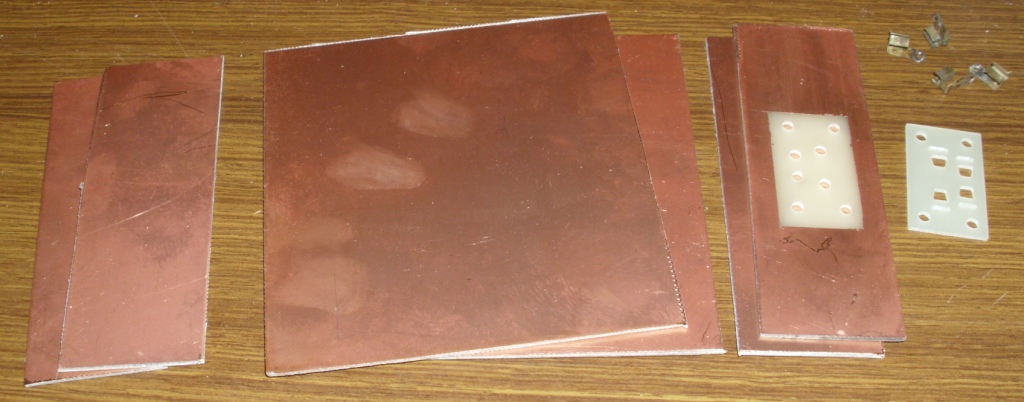
Figure 6: PCB Panels
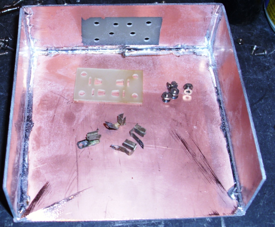
Figure 7: Tacking
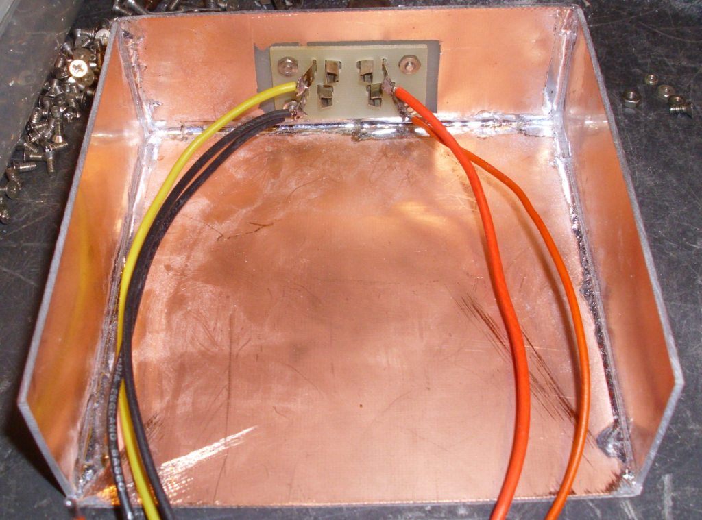
Figure 8: Wires
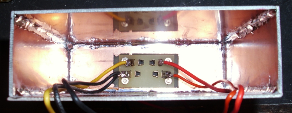
Figure 9: Box
Figure 10: Completed Case
BATTERIES
There were several different ways, in which I could add cells to
the battery. The battery needs to be 24 volts and tapped at 12 volts,
and 4 volts.
I could use ordinary cells, like Zinc-Carbon or Alkaline, of 1.5 volts each, and use penlight cells in holders. This would require 16 cells of AA size.
I could use NiCd or NiMh cells, of 1.2 volts each and make the battery rechargeable. This would require 20 cells of AA size.
I chose to use Lithium Ion cells, which at 3.7 volts each, require 6 cells, of 18650 size. These cells when fully charged are close to 4 volts each. If the battery is tapped at 1 cell, this would produce 4 volts for the receiver. If tapped at 3 cells, this would produce 12 volts for the receiver. There is enough room in the battery box to fit 6 cells to make 24 volts, and 1 extra cell for the receiver supply of 4 volts. I decided to use normal plastic battery holders, and this only allowed six of the 18650 cells to fit inside, so they were tapped at 4 and 12 volts. The cells have to removed and charged in an external charger.
The Li Ion cells have come down in price, as they are used in many power tools, laptop computers, and in hand held rechargeable torches. They vary in price, due to capacity. They also come in normal nipple ended cases, or with welded tabs. They are a little fragile and can be damaged easily, either by overcharging, fully discharging, or by short circuiting. A short circuit can result in extreme currents, rapid temperature rise, and possible fire or explosion. To overcome this possibility, there are several methods. There are normal battery holders. There are also controlled battery holders, which contain an IC and a power FET. This prevents overcharge, discharge, and short circuit. There is a special version of the cell, which has this built into the actual cell. You can choose your approach. Another possibility is using old laptop batteries. These can be disassembled, and the cells reused. Only one is usually faulty, and the rest are good. These are tabbed cells, so they can be soldered together. Fuses should be fitted to the new battery.
Figure 11: Cells and Battery Holders
CARDBOARD COVER
The green cardboard was unfolded, the old glue removed. It was taken
to a commercial copy centre. They printed new covers on thick paper.
I then cut and folded it, and added it to the outside of the box.
I also scanned the original cover on a computer. Alternatively,
these can be used to make a cover.
Figure 12: Scans of the green cardboard
Figure 13: Scans of the green cardboard
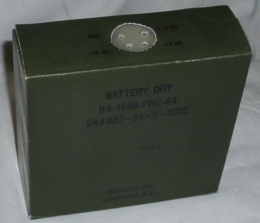
Figure 14: Completed Battery
Copyright
Ray Robinson vk2no