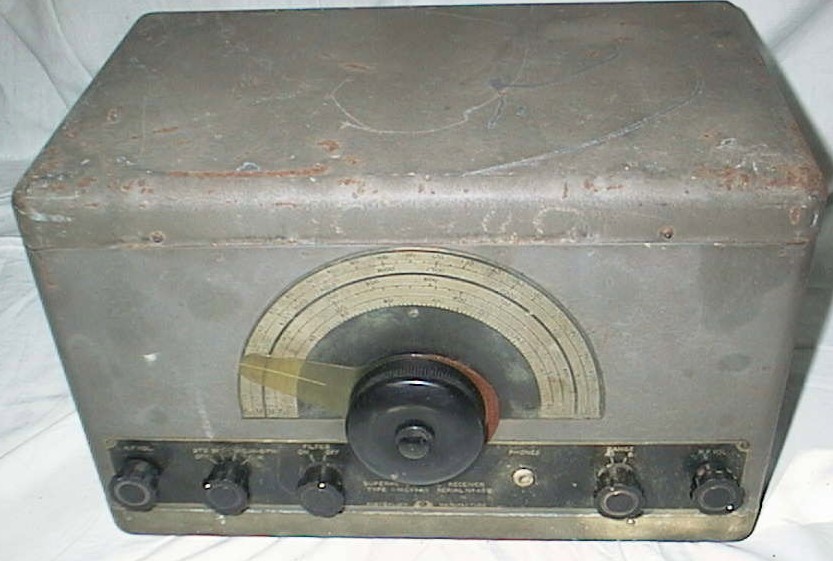
The C6940 is a receiver very
similar to the TELERADIO 3BZ radio, designed and manufactured by A.W.A.
(Amalgamated Wireless Australasia) over several years. The 3B and 3BZ types
were used extensively in the 1940s by "Coastwatchers". This receiver shares
many of the same features and was used on ships and shore stations during
the war.
There are three basic versions, the LONG WAVE model (Low Frequency) the MEDIUM WAVE model (Low and High Frequency) and the SHORT WAVE model (High Frequency). This article describes the Long and Short wave models.

LONG WAVE MODEL FRONT
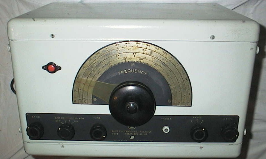
SHORT WAVE MODEL FRONT
PERFORMANCE
The LONG WAVE model radio is sensitive
for an low frequency receiver, but there is little traffic on these ranges
and a lot of noise. It is not as sensitive as a communications receiver,
as it only has one untuned RF amplifier for range A, and none for range
B. This LONG WAVE example provides a sensitivity on its ranges of:
A 6 - 25 microvolts,
B 6 - 15 microvolts,
(for a signal to noise ratio of
10 dB).
It receives the LF beacons quite
well.
The SHORT WAVE model radio is fairly
sensitive on the higher range. It is not as sensitive as a communications
receiver, as it only has one RF amplifier, the sensitivity being:
A 3 - 6 microvolts,
B 3 microvolts,
C 1 microvolt,
(for a signal to noise ratio of
10 dB)
It is usable as a short wave listener's
radio, and has very simple controls. It is easy to tune, with the slow
motion dial, but I find the dial pointer and no illumination not the easiest
to use. It can resolve SSB signals even with the fixed BFO. The RF gain
needs to be varied to adjust the BFO injection for different strength SSB
signals . This causes the BFO to change frequency which is annoying, but
after a while you develop a feel for it, and can use this interaction to
tune the BFO frequency.
This would perhaps be the ugliest radio I have ever seen and also one of the ruggedest radios around. It would probably survive any drop test, with perhaps just the dial cover and pointer broken if it landed on its face.
CONTROLS (LONG WAVE VERSION)
The front panel is dominated by a
large semi circular dial scale and a Muirhead slow motion drive and tuning
knob. The outside knob ring gives a 1:1 drive and the centre knob gives
a 56:1 reduction ratio. The knob cover and dial pointer are easily broken.
The frequency scale is etched on the semicircular brass plate with the
frequency coverage, and the letter of the range. All the other controls
are located in a horizontal line at the bottom of the front panel. There
is an etched strip that carries the knob labels, and model and serial numbers.
Some models also had a pilot light and a name tag in the top left and right
hand corners. The left hand knob is the audio gain control labelled AF
VOL, next is the 4 position function switch which is labelled OFF,
STANDBY, MCW SPH, CW. In the STANDBY position, the valve heaters
are on and the HT is off. MCW SPH is the normal operating position. In
the CW position, the BFO is turned on. There is no BFO frequency adjust
control. The next knob is labelled FILTER ON OFF and is used to switch
in a narrow passband filter. To the right of the centre tuning knob is
a jack for headphones, labelled PHONES. The next control is the frequency
range selector switch which is labelled RANGE and has 2 positions marked
A, B. The ranges are:
A 500 to
200 kcs (600 to 1500 meters),
B 200 to 15 kcs
(1500 to 20000 meters).
The last control at the extreme
right is the RF gain control which is marked RF VOL.
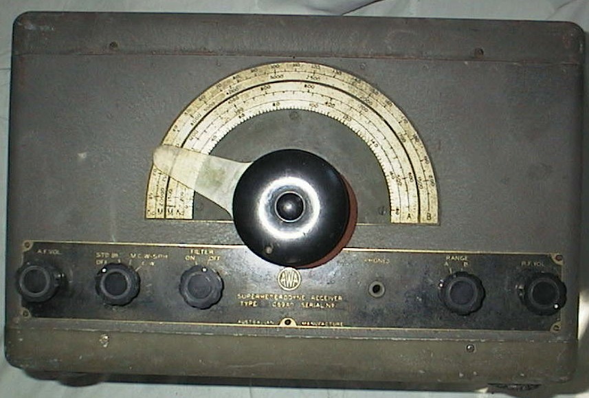
LONG WAVE MODEL CONTROLS
CONTROLS (SHORT WAVE VERSION)
The controls on the HF version are
basically the same as the LONG WAVE version. The differences are that the
third knob from the left is a TONE control as the HF model has no filter,
and the frequency RANGE selector switch has 3 positions marked A,
B, C. The ranges are:
A 9 to 26
Mcs (30 to 10 meters),
B 3 to 9 Mcs (90
to 30 meters),
C 1.4 to 3 Mcs
(200 to 90 meters).
DIFFERENT MODELS
The receiver came in several versions
denoted by a number in front of the C6940 model number.
This LONG WAVE example is a 3-12-C6940
serial number 456 (the 2 has a horizontal dash through it and is blacked
out). It covers 15 to 500 kcs, and requires external LT and HT.
This SHORT WAVE example is a 1-7C6940
serial number 715 and has a non factory installed mains power supply. It
covers 1.4 to 26 Mcs.
There appears to be several configurations
available:
1C6940 frequency 100 - 3000
kcs in 4 ranges, IF 95 kcs, 6U7 output, emergency crystal set 500kcs.
2-1C6940 frequency 100 - 3000 kcs
in 4 ranges, IF 95 kcs, 6U7 output, emergency crystal set 500kcs.
5C6940 frequency 100 - 3000
kcs in 4 ranges, IF 95 kcs, 6V6 output, emergency crystal set 500kcs.
7C6940 frequency 1.4 - 26 Mcs in
3 ranges, IF 535 kcs.
3-12-C6940 frequency 15 - 500 kcs
in 2 ranges, IF 535 kcs.
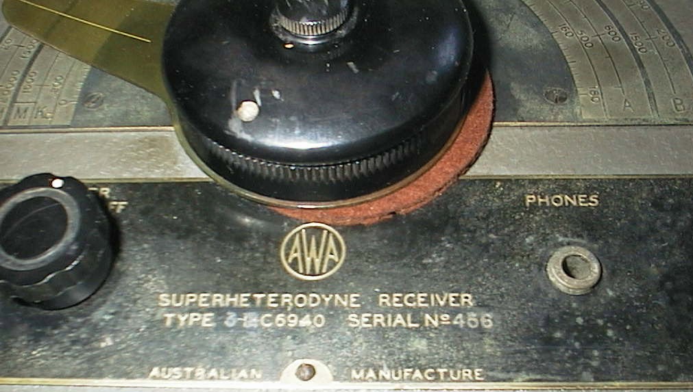
The cork washer under the main tuning knob is worn, has slipped out, and is visible in the photo above.
DESIGN
The C6940 is a conventional single conversion superheterodyne receiver using octal valves. Mechanically, the radio is very rugged. Electronically, it is very simple. It was designed to be a field portable, reliable radio. The LONG WAVE is different to the MEDIUM and SHORT WAVE versions.
The LONG WAVE version has a 6U7G as the RF amplifier, a 6J8G as the mixer, a 6U7G as the IF amplifier, a 6J8G as the IF amplifier and filter, a 6G8G as the detector, AVC rectifier, and audio pre-amplifier, and a 6U7G as the BFO. The audio output valve can be a 6U7G or a 6V6G. The IF frequency is 535 kcs. The LONG WAVE receiver has no power supply, but has terminals so that 250 VDC HT and 6 VDC LT can be brought in from outside. There is ample space on the chassis for a power supply, or a 500 kcs emergency crystal set. The RF amplifier is only used for range A and has an untuned aerial input circuit. The tuning capacitor is a dual gang type. One half is the local oscillator control and the other half is the grid input for the mixer.

LONG WAVE MODEL LAYOUT
The aerial and earth, HT and LT, are connected by passing wires through holes in the back of the steel case, and connecting them to press terminals. When the lid is removed it is easy to feed the wires through and press the terminals down for connection. They are all clearly labelled internally. The holes have a small rubber flap to prevent dust entry.
The SHORT WAVE version has a different valve arrangement, with a 6U7G as the RF amplifier, a 6J8G as the mixer, a 6U7G as the IF amplifier, a 6G8G as the detector, AVC rectifier, and audio pre-amplifier, and a 6V6GT as the audio amplifier. There is a separate 6U7G as the BFO. This example has a mains power supply with a 5Y3GT as the rectifier, but the installation does not seem to be of factory installation standard. The 535 kcs IF has such a high gain that it needs to be neutralised. It has a 3 gang tuning capacitor.
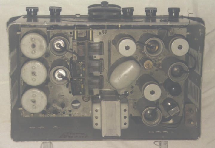
SHORT WAVE MODEL LAYOUT
The MEDIUM WAVE version has a different valve arrangement, with a 6U7G as the RF amplifier, a 6J8G as the mixer, a 6U7G as the IF amplifier, a 6G8G as the detector, AVC rectifier, and audio pre-amplifier, and a 6V6GT (or 6U7G) as the audio amplifier. There is a separate 6U7G as the BFO. The IF frequency is 95 kcs. It has a 3 gang tuning capacitor.
The case is a unique design, made of heavy steel, plated, and then painted grey crackle. The case consists of a spot welded main front, sides and back, with removable top and bottom covers. The top cover clips on, and the bottom cover is held on by screws. The case has rounded corners and is nearly indestructible! It is very strong. There is also a front cover that clips on to protect the front panel controls. The front covers are not commonly found. There is a normal style "U" shaped steel chassis screwed inside the steel case. The same style case was used for other radios and test instruments, and came in various sizes. Some cases have ventilation slots covered by mesh, and some have none. There are four rubber feet on the case bottom for normal use. These have usually become hard and flattened, or lost. It was also possible to attach a bottom cover to a top cover with long screws and so a transmitter and receiver could be permanently mounted to each other or fixed to a table. The case is the same stamping as the 3BZ case, and the holes used for the speaker and headphone leads on the side, are cover by a steel plate, riveted on.

The chassis is painted grey. The capacitors and resistors in the HF model are mounted on two tag boards located below the AF amplifiers and near the BFO. In the LF model, they are mounted on the BFO and Filter mounts. The resistors are the body/tip/dot type and the capacitors are the black pitch encased AWA type with the brown paper label. The HF version has been recapped. The C6490 has point to point wiring and it quite busy underneath. The RF section has a long rotary gang switch. The HF version has integral metal shields and coils mounted on the switch. The RF coils that are mounted horizontally on the shields are difficult to adjust. Individual bypass capacitors are mounted on the valve pins and are quite hard to access. The LONG WAVE version has 4 cans under the chassis for the BFO and the filter. The audio output transformer is mounted underneath the chassis.
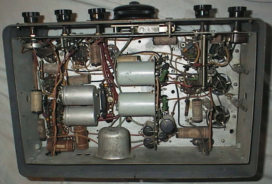
LONG WAVE MODEL WIRING
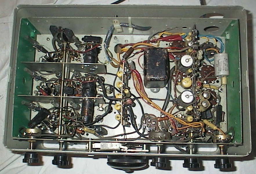
SHORT WAVE MODEL WIRING
RESTORATION
The LONG WAVE receiver was in a reasonable on the outside and perfect condition on the inside. The valves, valve shields and output transformer were missing. It was cleaned and the missing components added. The resistors and capacitors were good so they were not replaced. The SHORT WAVE version has several modifications, so these were reversed, except for the power supply addition. It was left in, but tidied up. The function switch wiring was corrected. The valves were all good and most components were OK, so they were not replaced. It had been partially recapped, so I decided to replace them all. The outside has been painted a gloss light grey, and inside a liberal use has been made with a hand brush, painting the valve shield, IF and coil tops, choke, and power transformer. there is a signature in red paint on the back inside wall. I presume it was the previous owner, "VK2AJY TOUKLEY" in N.S.W.
The LONG WAVE receiver had a binding dial, so it was disassembled and lubricated. A missing knob was replaced. I applied an external power supply and found the audio was working properly. I had no manual, so I used a signal generator to discover that the IF frequency was the same as the 3BZ, so I peaked the IF coils for 535 kcs. I didn't know which slugs and trimmers were for which band so I experimented until I found which were the correct ones. I aligned the coils for each range, using the coil slugs for the low frequency end, and the trimmers for the high frequency end of the range. The trimmers are large piston types, bolted to the chassis and are visible in the under chassis and top views. You need a tube spanner to loosen the lock nut, and then the pistons can be pulled up and down easily. I fabricated a tube spanner from a short length of copper water pipe and filed the flats on the inside of one end. Don't loosen the nuts off too much, as the pistons can fall out if you turn the radio over. Also check that the trimmers are bolted to the chassis securely, that you havn't loosened them, otherwise the alignment will be inaccurate and the receiver noisy. The alignment was straight forward.
The SHORT WAVE receiver has a mains power supply, so I plugged it in to 240 VAC and turned it on. I then turned the function switch to STANDBY and checked all the valves. I turned the switch to the next position and tested the audio. I then began the alignment with tuning the IF to 535 kcs. I set the BFO frequency and then began on the RF ranges. The ranges A, B, and C, aligned properly with the normal capacitive trimmer for the high end and slug trimmer for the low end of the band. The trimmers are the same large piston types, bolted to the chassis and visible in the under chassis view. Range A proved troublesome as during alignment at the high end, the radio began motor boating (mixed high and low frequency instability). I discovered the neutralising capacitor was disconnected so I reconnected it and the radio became well behaved.
Both the radios now sit on the shelf next to the 3BZ (C6770) as an ugly trio.
REFERENCES
An Economical Commercial Receiver of Wide Application, Stacy J.B. and Holloway F.S., AWA Technical Review Vol. 5 No. 2, 1940, P 61-75.
Instruction Book NO. 1-69400R, 6 VALVE M.F. MARINE RECEIVER A.W.A. TYPES 1C6940 & 5C6940, 7 November 1946
Marconi School of Wireless, Communication Receivers (2-1C6940 - 7C6940)
1C6940 MEDIUM WAVE (circuit)
1C6940 MEDIUM WAVE (simplified circuit )
1C6940 MEDIUM WAVE (circuit)
5C6940 MEDIUM WAVE (circuit)
1,5C6940 MEDIUM WAVE (top layout)
1,4,5C6940 MEDIUM WAVE (wiring layout)
2-1C6940 MEDIUM WAVE (circuit)
7C6940 SHORT WAVE (circuit)
C,2C1562 CRYSTAL RECEIVER (circuit and layout)
Thanks to Dave Prince
Written by Ray Robinson VK2ILV