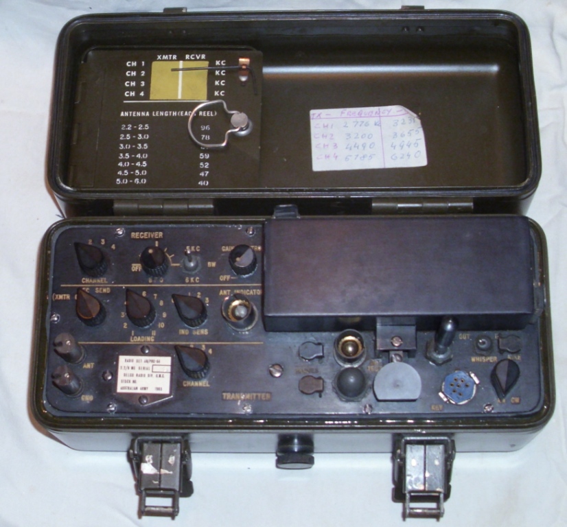
Figure 1: PRC-64A
The AN/PRC-64 is a transistorised HF transmitter receiver used in the Vietnam war. The transmitter and receiver are independent, and each have 4 channels, set by individual crystals. The frequency coverage is 2.2 to 6 mhz. The receiver runs from 4 volts DC, and can receive AM, CW, and SSB. There is a choice of 2 bandwidths of 6 khz and 0.5 khz, selected by a switch. The transmitter can produce 5 watts output on CW, and 1.5 watts output on AM. It uses 24 volts and 12 volts DC. The power is provided by a single plug in dry battery, type BA1509. There is no provision for external power. The receiver uses a small crystal earpiece, of a similar type used on 1960s transistor radios. The transmitter uses a small microphone, that mounts on your finger and looks like a ring, with a crystal earpiece type cord. There is an accessories bag, that contains long wire antennas, and an external morse key. The radio is 5 inches high, 4.5 inches deep, 10 inches wide and weighs 7.25 pounds. This radio replaced the GRC-9 portable transmitter receiver.
The PRC-64 was upgraded to the PRC-64A by adding a small internal board to increase the keying speed to 300 wpm. This example is a PRC-64A as noted on the case, but PRC-64 on the nameplate. The serial number is 61 and it is dated 1965 and used by the Australian Army.
Figure 1: PRC-64A
HISTORY
The radio was originally designed in the early 1960s for the CIA,
called the Delco 5300, and intended for clandestine use.
It was adopted by the Army Special Forces, and was used by the
Australian Army and issued to the SAS. The original manufacturer was the
Detroit Motor Company and the case has Delco Radio Div. G.M.C.
on the top. The radio is HF which uses skywave and has a longer
range than the VHF radios which use ground wave. Skywave also has
better range in jungles than VHF.
DIFFERENCES
The PRC-64 and PRC-64A have a frequency range of 2.2 to 6 mhz, in 4 bands,
2.2 - 2.85 mhz,
2.8 - 3.65 mhz,
3.6 4.70 mhz,
4.6 6.00 mhz.
The Delco 5300 and Delco 5300C have a frequency range of 3.0 to 8 mhz
in 4 bands.
The chart under the lid (showing crystal channels, and antenna lengths)
on the early PRC-64 and Delco 5300 are marked in kc, and the later
PRC-64A and Delco 5300C are marked in mhz.
The front panel of the 5300 is very similar to the PRC-64, except for the RED knobs, the antenna terminals, the lack of a bandwidth switch, and the morse key does not have a microswitch under it. The receiver printed circuit board is smaller, as it does not have the 2 receive filters. The transmitter board looks the same, but it does not have the fast keying modification. The modulator board is different.
The front panel of the 5300C is also very similar to the PRC-64, except for the RED knobs, the lid operated battery switch is missing, there is a 6 pin connector, and the morse key also has no microswitch under it. The 6 pin connector looks like an ordinary U/229 type but has an extra contact in the middle. Plugging an H-250/U handset on this does not work, but causes the radio to go into transmit and audio feedback occurs. The case has butterfly latches that rotate to close it. The receiver looks the same, but it has different coil slugs. The transmitter board looks the same, but it has crystal sockets, the same size as the receiver. It does not have the fast keying modification. The modulator board is almost the same.
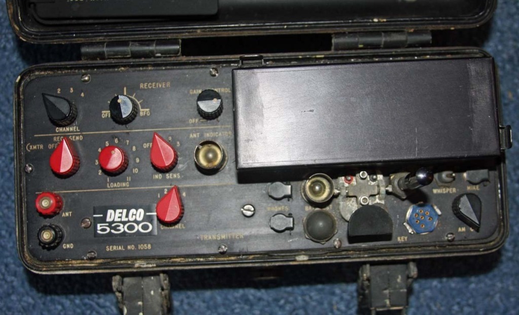
Figure 2: Delco 5300
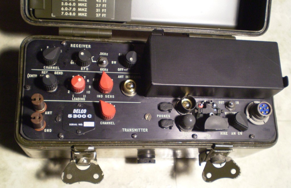
Figure 3: Delco 5300C
CONTROLS
The PRC-64 has all the controls on the front panel.
They are neatly divided into receiver and transmitter controls.
At the top right is a cover for the plug in battery.
Located at the top left are the RECEIVER controls, which are the 4 position receive CHANNEL select switch, the BFO control (including an OFF position), the 2 position bandwidth switch (labeled BW), which selects 0.5KHZ and 6KHZ bandwidths, and the GAIN CONTROL with the receiver OFF switch.
Immediately below this is the REC and SEND switch, with the information that in the REC position the transmitter is off (XMTR OFF). Then there are three antenna controls. The variable LOADING control is labeled with 11 positions, but is a variable inductor intended to add inductance to a long wire antenna for the best loading. To show the best loading there is an antenna current lamp labeled ANT INDICATOR. The 4 position sensitivity switch labeled IND SENS, can turn this lamp OFF, or select 3 different sensitivities.
At the bottom left hand side are the antenna and ground terminals, labeled ANT and GND. Then there is the nameplate, and then the 4 position transmit CHANNEL select switch. To the right of this are 2 miniature receiver phone jacks with spring covers, labeled PHONES. There is a battery test switch and lamp labeled BAT TEST. To the right of this is a small morse key, labeled KEY, and used for sending CW. There is a multi pin socket for connecting an external key or a burst encoder, such as the GRA-71 type. Next to this is the 2 position transmitter mode switch which selects AM or CW. Above this is a small toggle switch to enable more gain when the operator needs to use a quite voice, labeled WHISPER IN and OUT. There is a small covered phone jack for the microphone labeled MIKE. There is also a large tall post, that is a battery isolate switch, and when the cover is closed, the switch is activated which disconnects the 3 battery voltages.
There is a deep battery box, that holds the plug in battery, and it is kept in place by a spring latched cover.
The top of the case closes to provide a water proof seal on the radio. In the top cover, is a small accessories box. It holds 2 crystal earpieces, the microphone, 2 spare lamps, and an allen key for the knobs. On the lid of the box is a table, so that the channel frequencies can be recorded. Note that the receiver and transmitter are independent, so the receiver frequency does not necessarily have to be the same as the transmit frequency. Also on the lid is a chart, showing the correct antenna length for the required frequency.
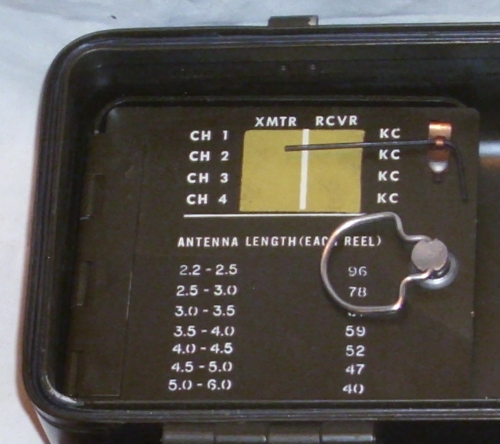
Figure 4: PRC-64 Chart
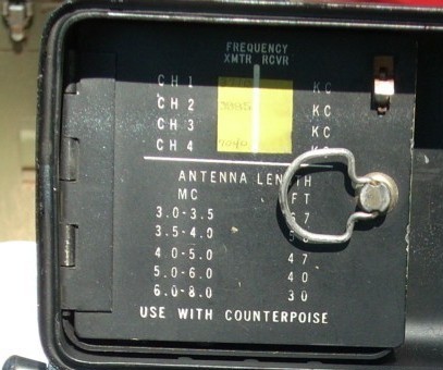
Figure 5: Delco 5300 Chart
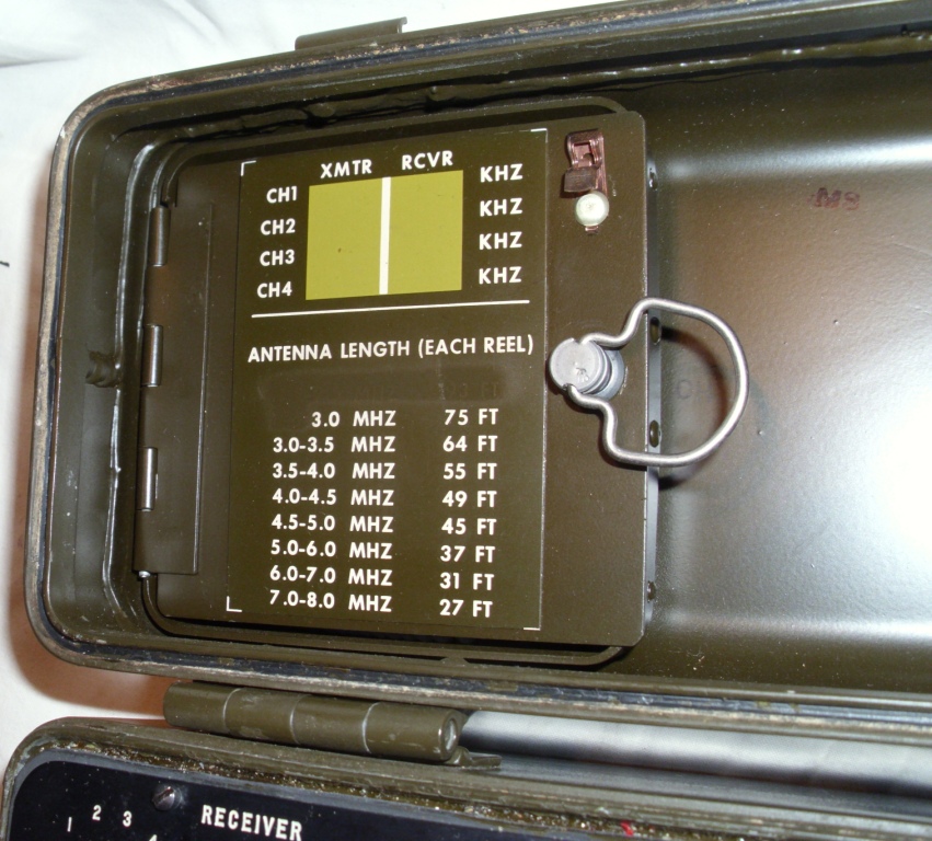
Figure 6: Delco 5300C Chart
MECHANICAL DESIGN
The radio is constructed around the front panel. If you consider
the radio as being divided into 2 parts vertically, and into 3 parts
horizontally, then it can be roughly partitioned into 6 physical
blocks. The battery compartment uses 2 of these blocks, the receiver,
the transmitter, the antenna network, and the modulator use 1 each.
The battery box and antenna network box are welded together and to the
front panel, which provides rigidity, and allows the other modules to
be mounted on them. The receiver is at the top. The transmitter and
modulator are at the bottom. The front panel is attached to the case
with 10 screws and a watertight gasket. The case is in 2 halves that
open out. This is waterproof when closed. There is a pressure release
valve on the case, which indicates a pressure tight seal, and also the
possibility that the radio was transported by aircraft. When the radio
is removed from the case, you will find 2 alignment tools and a plastic
alignment chart inside.
RECEIVER
The receiver contains 10 transistors, and is constructed on 2 printed
circuit boards, attached to each other. It uses a D15 connecter to
connect to the radio. The PNP transistors use a positive rail
connected to the emitters, and the collectors are grounded.
The antenna comes in and enters the first RF amplifier, which has
a single tapped tuned circuit in its base, and another in its emitter.
This is then capacitor coupled to the second RF amplifier and then to the
base of the mixer. The crystal oscillator is also injected at this
point, and operates 455 khz above the received frequency. There are
only 2 tuned circuits and 1 crystal per band. The 4 position band
switch selects the appropriate tuned circuits and crystal.
The PRC-64 receiver uses a CR78 (HC25) crystal with a 5 mm.
The mixer output goes through an IF tuned circuit, through 2 IF
amplifiers, and then to another IF tuned circuit, before reaching
the diode detector. Between the IF amplifiers are 2 switchable IF
filters, wide or narrow (a 6 khz ladder filter or a 0.5 khz Collins
mechanical filter). The detected audio goes through a 2 transistor
audio amplifier to the phones output. There is a single transistor
BFO, injected into the second IF amplifier. There is a single
transistor AGC amplifier, that controls the RF amplifier and first
IF amplifier. All the transistors are 2N2401, except 3, the AGC
amplifier and the 2 audio amplifiers, which are DS-46W type.
The receiver has its own ON/OFF switch, and is completely independent
to the transmitter. The only things it shares, are the antenna coupling,
the case, and the battery. It draws 14 mA at 4 volts DC.
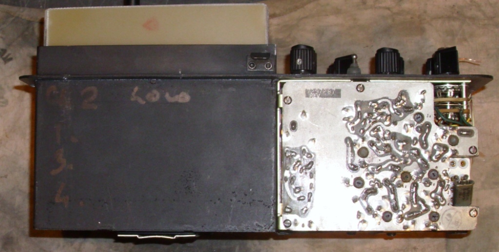
Figure 7: Receiver PRC-64
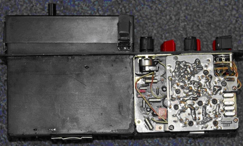
Figure 8: Receiver Delco 5300
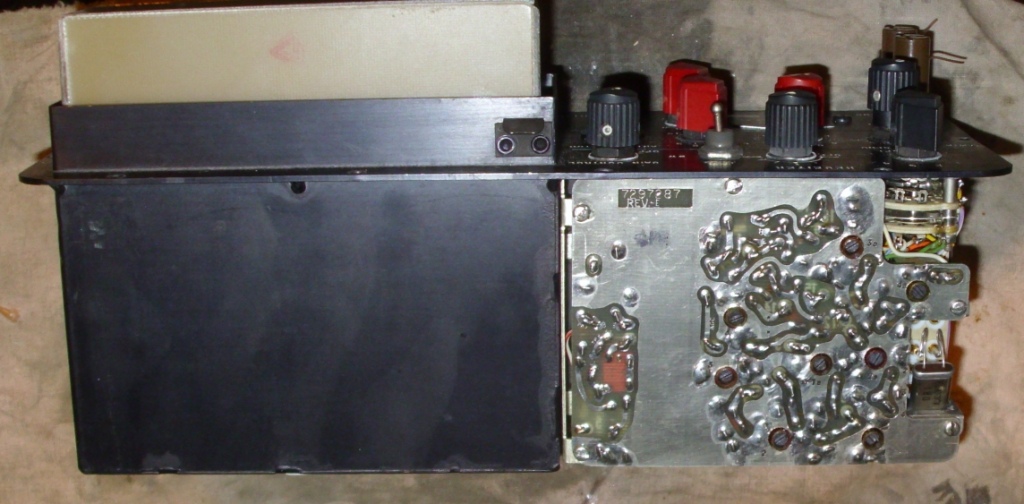
Figure 9: Receiver Delco 5300C
TRANSMITTER
The transmitter is a separate module with one main PCB that uses
a D15 connector to connect to the radio. It uses 4 NPN transistors
connected in a conventional arrangement, with positive on the
collector and emitters to ground. The crystal oscillator uses
a 2N2951 transistor, and is always on in the AM mode. When in
the CW mode, it is enabled by the morse key or external keyer,
but has a circuit to keep it oscillating when the key is released,
but for a short time only. This is to prevent any slow starting or
chirping. There is a little add on PCB near the crystals, containing
6 components, that keeps the oscillator running for a short time.
This is the difference for the PRC-64A. The oscillator output is
capacitor coupled to the RF driver transistor, type 2N1506A.
This has the keyed voltage on it, with no delay function, to ensure
clean CW. This is coupled through a tuned circuit to the RF power
amplifier. It uses 2 transistors of type 2N2782. It always has
voltage on it, when the transmitter is turned ON. There is a tuned
circuit on the output. There are only 2 tuned circuits and 1 crystal
per band. The 4 position band switch selects the appropriate tuned
circuits and crystal. The PRC-64 transmitter uses a CR89 (HC32)
crystal with a 7mm pin spacing, so that receive and transmit
crystals cannot be swapped. The transmitter draws 380 mA at 24 volts
when running CW, and 200 mA when running AM. The manual says 700 mA for CW.
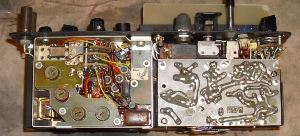
Figure 10: Transmitter PRC-64 (transmitter left, modulator right)
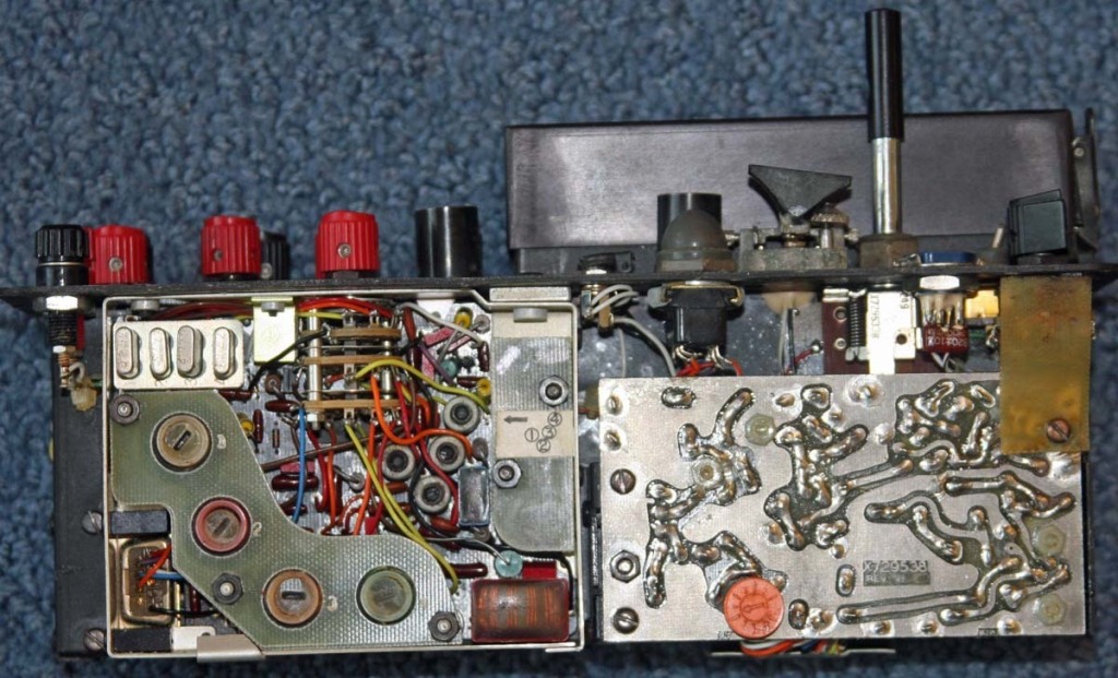
Figure 11: Transmitter Delco 5300 (transmitter left, modulator right)
Figure 12: Transmitter Delco 5300C (transmitter left, modulator right)
MODULATOR
The modulator is on a PCB and is located next to the transmitter PCB.
It has 2 PNP transistors 2N404 type, and set up like the receiver,
collectors near ground, and positive voltage on the emitters.
The microphone jack is connected to a 2 stage audio amplifier, which goes
to a transformer, which is used to amplitude modulate the transmitter.
The amplifier has a gain switch, that is used for the whisper mode.
When in CW mode, the audio amplifier is connected with positive
feedback, causing oscillation, and this is used as the keying sidetone.
There is another PNP transistor type 2N3213, that is controlled by the
morse key and external keyer, and this keys the battery voltage to
control the transmitter RF driver amplifier and produce the CW.
The modulator consumes 3 mA at 12 volts DC for AM, and 1.5 mA for CW.
Underneath the modulator PCB, is the battery isolate switch, and
the battery TEST switch. The TEST switch (which is active all the time)
connects a 100 ohm resistor as a load for the 24 volt battery,
and drains 350 mA.
It uses a Zener diode and a PNP transistor type 2N3213 to drive a
lamp. The lamp will light if the battery voltage is greater than 20
volts.
ANTENNA COMPARTMENT
The antenna box contains the loading control which looks like a
VARIAC autotransformer. It is used to add extra inductance for
antenna loading. There is a lamp that is used to show the antenna
current. Its sensitivity is controlled by a switch and some
resistors on a small PCB. The antenna compartment also contains
the REC/SEND switch, and the receiver and transmitter connectors.
It can only be accessed by removing the receiver.
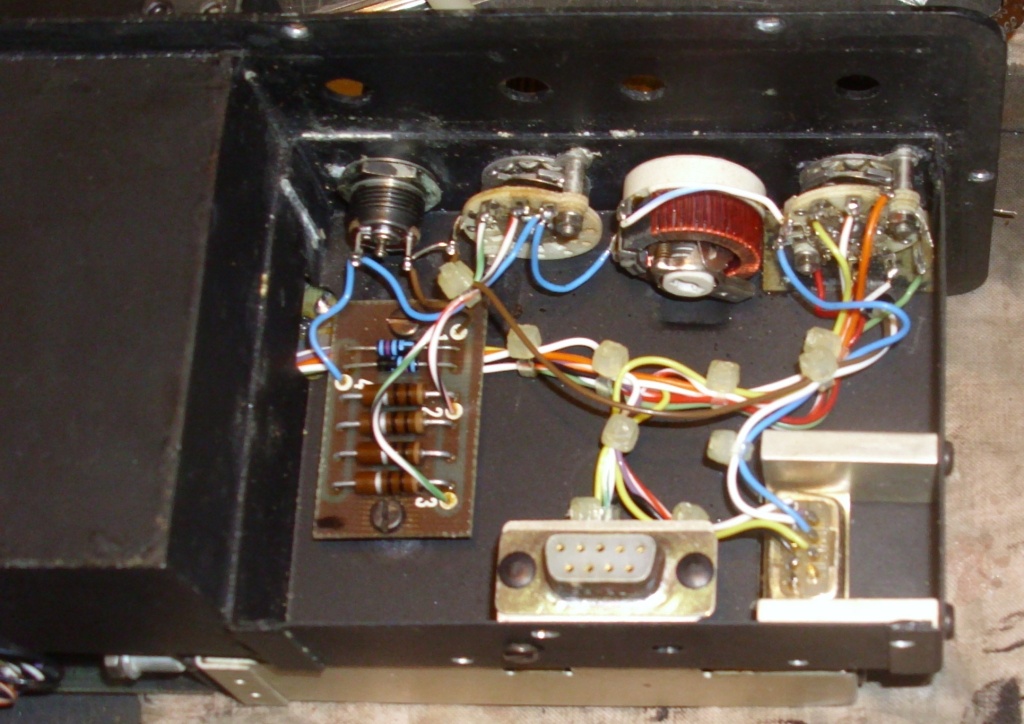
Figure 13: Antenna box
BATTERY
The first problem when using the radio is battery power.
A PRC-25 battery connector
was found to be approximately the correct size to mate with the
PRC-64 battery connector. This was wired to a battery holder and
3 alkaline penlight cells, to provide 4 volts for the receiver.
The transmitter required 24 volts and 12 volts. I used some 3.7
volt Lithium Ion cells, recovered form a dead laptop battery.
It had several type 18650 cells, and only one was bad. I wired
6 of these in series, producing 24 volts, and tapped it halfway
for the 12 volt supply. The battery test switch worked. I
disassembled a real BA1509 battery and saw that the original
arrangement used a single 24 volt battery made of 2 inch diameter
button cells, and it was tapped at 12 volts and 4 volts, with a
common negative.
RESTORATION
There was nothing wrong with the PRC-64 and the Delco 5300C,
but the operator had a few problems with familiarization.
The IF was aligned at 455khz, but it was very close and did
not really need adjustment. I had to make up an extender cable
to access the antenna box, and to align the IF. It was a simple
cable with a D15 on each end.
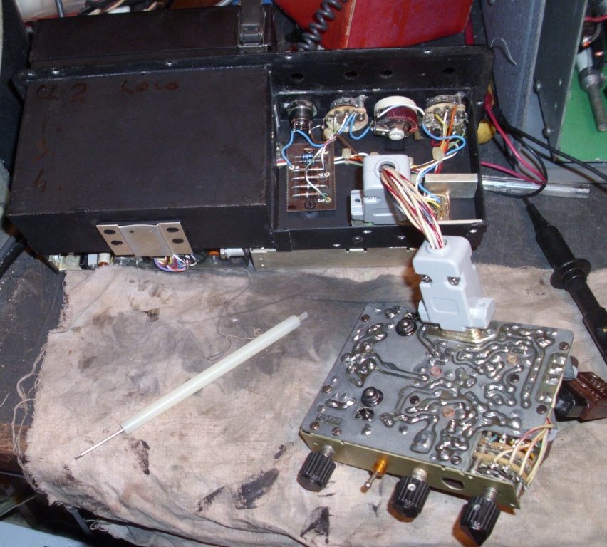
Figure 14: Extender cable
The 4 channels each have different frequency coverage, and I originally had the crystal in the wrong channel socket, which meant I could adjust for maximum received noise, but no signal was heard. I realised this, when I tuned the signal generator to the image frequency. There are only 2 adjustments per channel. I was using BC-611 crystals, of the FT243 size, hanging out on leads, and used the 3590 and 4045 khz crystal pair for testing. This proved unreliable. Several times, I went looking for a fault when the receiver stopped working. I eventually used some small cheap common crystals for testing. These were the 3579.545 khz NTSC TV colour burst crystal, and the 4433.619 khz PAL TV colour burst crystal. These were wire ended and I just soldered them to some small pins and plugged them in. They were 100% reliable. Using the correct crystals resulted in good performance, with a 0.5 uV sensitivity for 10 dB S/N. I ordered some crystals for the 80 meter amateur band, and while the receive crystal was available in the correct holder, I had to settle for a wire ended crystal for the transmitter. The transmitter aligned easily and produced 5.6 watts on CW and 1.5 watts AM.
ACCESSORIES
The normal accessories are contained in the small compartment
in the top lid. They are a small microphone, that attaches to your
finger, like a ring. Also 2 crystal earpieces. There are 2 spare
light globes in clips, and an allen key for the knobs, also in a clip.
Inside the case, underneath the front panel, is a plastic alignment
chart, and 2 alignment tools in clips. The radio comes in a green
cloth bag, which has a pouch on each end. In the pouches are 3 metal
spools of wire. One contains an antenna feeder, and the other 2 are
halves of a dipole antenna, with length markers. The external morse key is also in the pouch.
The pouch can be attached to a belt or webbing, to allow it to be
carried on the body.
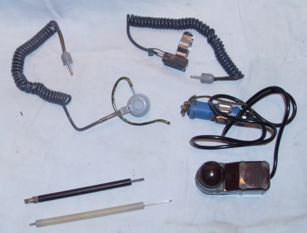
Figure 15: Accessories
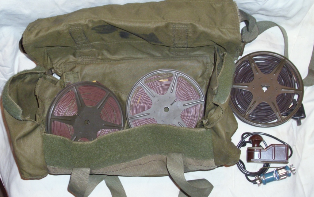
Figure 16: Bag
OPERATION
The radio is easy to use, the controls well laid out and the
functions are obvious. The receiver is completely independent,
and draws very little current. The separate crystal for transmit
and receive, means that cross channel operation is possible.
The transmitter loads into an antenna easily and has a simple
loading control and load indicator. The built in morse key is
helpful. The small size, low weight, and a carry bag with antennas,
makes a very easily transportable radio.
The radio has limitations. It runs on battery power, and 3 different voltages are required. The batteries are unavailable, so you have to build your own. The frequency range is small, only 2.2 to 6 mhz. There are only 4 receive channels, and you need a crystal for each channel. I found the crystal earpiece awkward and would prefer headphones. The transmitter has the same frequency limitation and number of channels, and the feature to prevent crystal swapping, has resulted in an obsolete and difficult to source crystal holder, and the necessity to wire in the transmit crystals. The built in morse key has a microswitch, so it has a poor feel, and looks fragile. The external morse key is better. The Delco 5300C is easier to use, as it has the same crystal style, a better morse key, a better frequency range (covering the 80 and 40 meter amateur bands), and better case latches. However, the PRC-64 is more common.
REFERENCES
TM 11-5820-552-15 Radio Set AN/PRC-64A Operator, Organizational, DS, GS, and Depot Maintenance Manual Including Repair Parts and Special Tools, November 1970.
Making a BA1509 battery for the PRC-64
Copyright
Ray Robinson