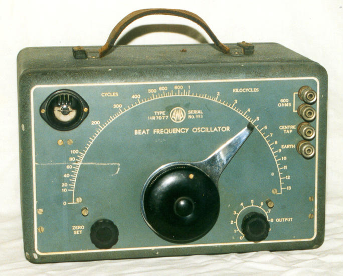
The Beat Frequency Oscillator (BFO) is an audio oscillator made by A.W.A. (Amalgamated Wireless Australasia) in 1943. The BFO is intended as an audio source for the testing of audio equipment, and it produces sine waves from 10 cps to 13 kcs at variable amplitudes. The output is balanced, and it provides a high drive level of 10 volts into 600 ohms, or 30 volts into an open circuit. It can be used for testing speakers and lines, or the output can be adjusted (attenuated) to low levels, for inputs on amplifiers. It is a general purpose test instrument.
SPEAKERS
When you acquire a radio with a damaged speaker or without a speaker, you need to use one from your spares. The most obvious feature is the size and that will be your first selection choice. The next may be the type of magnet. Then the voice coil impedance. The final criteria will be whether it works or not. For a static display this is irrelevant providing it looks good. For a good sounding radio, it is important that the speaker works properly. You can use a multimeter on the ohms range, and check for continuity, at the same time listening for a click, and if it is good, trying it in the radio. You can do better than this and save some time, by testing it with the oscillator. Connect it directly to one of the 600 ohm output terminals and the centre tap, and tune the oscillator through the range. This will show how well it works and the frequency response. There will not be enough drive from the oscillator to test the full power output of the speaker, and you will need an amplifier if you wish to test the speaker power output. The frequency response may not be completely equal (flat) across the whole range, as most speakers cannot reproduce very low frequencies or very high frequencies. The speaker should produce all frequencies as a pure tone. Any harshness, crackles, or noise may indicate a problem.
If the sound is too soft it may be increased a little by using a transformer. A 600 to 3 ohm speaker is best, often found on line matching speaker enclosures. This will provide a better impedance match between the oscillator and the speaker and thus it will sound louder. Also, an ordinary speaker transformer from your spares box, connected to the 600 ohm terminals on the oscillator, and to the speaker, will be suitable. Speaker impedances are low, usually around 3.5 ohms. Speaker transformers match the output valve impedance (which may be in the range of 5000 ohms) to the speaker. A speaker transformer from a transistor radio may be a better choice for testing speakers with this oscillator, as output transistors have an impedance in the range of a few hundred ohms. Use what you have in your spares box.
Impedance matching is important for efficient radio performance, but is not critical for bench testing these audio parts. In this case, impedance can be simply considered as the AC resistance of a device (although it is more complex than that). If the impedances are the same (matched) then coupling of radio waves is efficient. If not well matched then performance is not the best it can be. The aim of these tests is to verify that a speaker works across the range, rather than its power output, so an approximate match is all that is necessary.
This may be a good time to go through all your speakers and output transformers to find out which ones are good. Label them. Keep the faulty ones as they may be useful for parts or for a static display.
HEADPHONES
These can be tested in the same manner as speakers. Low impedance headphones will be fine when connected across the 600 ohm oscillator terminals (or from one to the centre tap), and full oscillator output probably won't be required. High impedance headphones may require a higher output setting or even a transformer. In this case, a speaker transformer with the low impedance winding connected to one 600 ohm terminal and the centre tap, and the high impedance winding connected to the headphones, may help. The frequency response of headphones is usually not as wide as speakers. Hi-Fi headphones are an exception.
TRANSFORMERS
You can test your speaker transformers by connecting them to the oscillator. Connect the transformer to the 600 ohm output terminals on the oscillator. You can monitor the output with a speaker and listen to the output which should be a pure tone. A pair of headphones will work just as well. An oscilloscope is the best way as you can see the wave form.
You can test your audio transformers too. Keep in mind that an inter stage transformer is meant to match a plate circuit to a grid circuit, so both windings will be a higher impedance than a speaker output winding. So connect the transformer to the 600 ohm output terminals, and use a pair of high impedance headphones or an oscilloscope. If these are not available, use a speaker transformer and speaker. You can also test an audio transformer with a multimeter, and this will show an open circuit winding, but it may not indicate a short circuit or winding damage.
AUDIO AMPLIFIERS
Most radios have some sort of audio amplifier in them. It may consist of a preamplifier valve, with a power amplifier to drive the speaker. These can be tested with this oscillator. Connect the 600 ohm output terminals to the radio and check its performance. One terminal should be connected to the radio chassis and the other via a capacitor to the grid of the output valve. The capacitor is to stop any DC conditions being upset, and to protect the oscillator should you touch it to the wrong pin on the valve socket. The value should be about 0.1 micro farad and about 400 volts. (Use a capacitor in both leads for hot chassis sets.) When connected to the grid of the output valve you should be able to hear the oscillator in the speaker, and you can adjust the oscillator level and frequency to check the function. If this proves to be working well, you can check the preceding stage (if it has one). Once again connect it to the grid of the preamplifier and check the performance. You will have to reduce the output of the oscillator. The tone heard in the speaker should be clean, without harshness. If it is not, then fix the fault and retest.
One example I had, was a distortion that occurred at high volumes in an AWA radiolette. By using the oscillator and injecting it into the audio amplifier, I found out that it was the speaker support. The speaker cone spider had a crack in it which rattled with large speaker cone movements. Once found, the fault was fixed with a little glue, but finding it was the problem. The oscillator made it easy to locate.
MILITARY USE
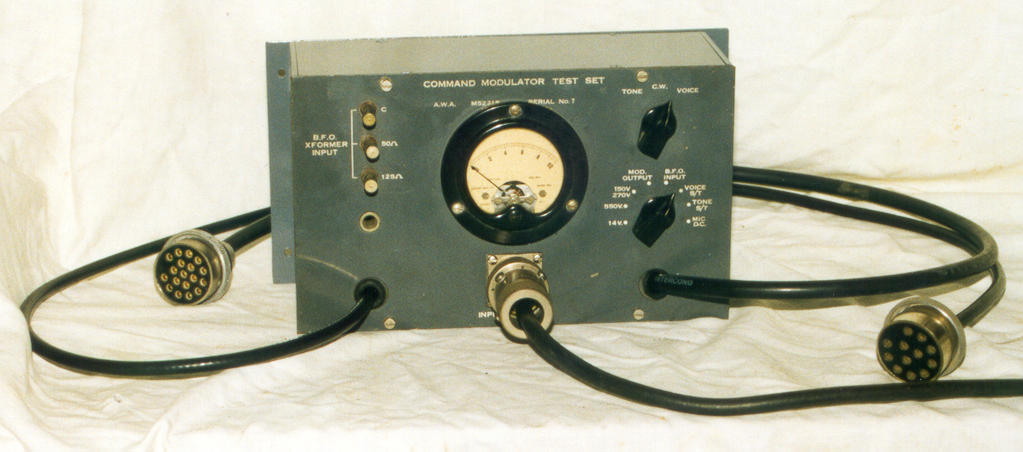
After the war, there were military aircraft radios which were no longer needed, and several of these types were used in Civil Aviation. One such radio set was the SCR-274N which was sometimes called the "Command Set" or "ARC-5" even though this name was not quite accurate. This was a modular system with individual receivers and transmitters with a separate modulator. A.W.A. serviced these radios and some can be found with 1958 tags and 12 volt conversions (they were originally made for 28 volt aircraft). A.W.A. made test sets so that they could be tested on the bench and one such test set was the M52215 Modulator Test Set for the BC-451 modulator. The test set was used to test all the modulator functions including the amplifier which required audio input, and it used the A.W.A. R7077 BFO as the signal source. The input terminals are labelled BFO XFORMER INPUT and have 2 impedances. When the switch on the M52215 is switched to the position labelled BFO INPUT the input can be adjusted to the reference level. The switch can the be set to MOD. OUTPUT to measure the amplifier output. The switch position next labelled VOICE S.T. measures the level of the audio that is sent to the receiver as a side tone. (A "side tone" is some of the transmit audio that is sent to the receiver, so you can hear what you are transmitting). The modulator can then be serviced using this oscillator to test the audio sections.
CONCLUSION
The BFO is a perfect audio oscillator for testing valve radios. It is easy to use, has a single frequency control, can be adjusted for low level amplifier inputs, or can even drive a speaker. This makes it simple to determine if any distortion is from the speaker or the amplifier, if there is any hum at full output, and if there is any abnormal frequency response. The BFO transformer output prevents the load from affecting the frequency, and protects the oscillator output circuits. It's obsolete name and appearance, looks good sitting on the test bench next to older test equipment. The BFO is very useful for fixing valve radios and would be a useful addition to your radio test gear.
REFERENCES
Instruction Book No. 3-7077R, A.W.A.
Copyright
Ray Robinson