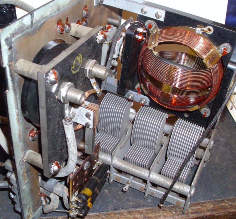
Figure 1: Variometer and Capacitor
The AERIAL COUPLING EQUIPMENT C (AUST) allows an aerial to be remotely located, and matched to a WIRELESS SET No.11 (Aust.). The equipment contains a variable capacitor and a variable inductor. The inductor is an unusual coil, as it is air cored, has no former, the turns are double spaced, and it is a variometer. I have a second unit, in which the variometer was damaged and I wished to repair it.
Figure 1: Variometer and Capacitor
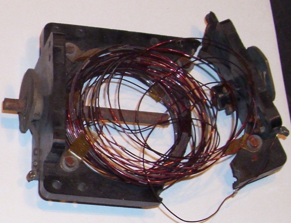
Figure 2: Damaged Variometer
The variometer was disassembled. The bakelite frame was broken. This was clamped and repaired with epoxy glue. The coils were removed and were inspected for damage. There are four coils, two on the inside that rotate, and there are two on the outside that are fixed. Two of the coils had been bent and distorted, and one had completely unraveled. The glue or lacquer that held the turns in place and in shape, was brittle and falling off. There were little plastic braces that held them together, but these were not damaged.
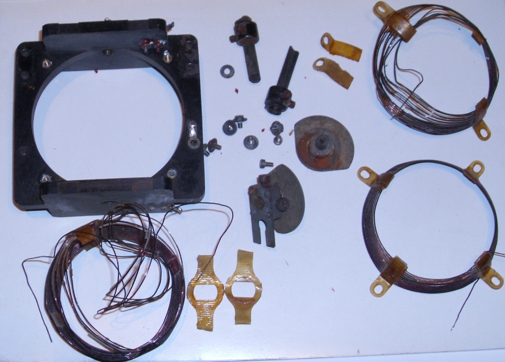
Figure 3: Variometer Parts
COIL LACQUER
I needed some liquid to glue them back together, something that would not reduce the Q of the coil. Nitrocellulose lacquer was a possibility. Another was polystyrene, as many coil formers were made of this material. I knew tool maker who had worked at AWA. He told me how he designed and constructed a lathe that would wind a cylindrical coil. The coil was air cored, supported by four polystyrene ribs. The manufactured coil could be any diameter, any length and the winding pitch could be varied. The wire was heated during winding, so that it partially melted into the supporting four parallel ribs.
I tried to purchase polystyrene cement at my local hardware store but they did not have any. I avoided going to a hobby shop, as the small quantities I had seen were expensive. Commercial coil dope is available, but it is in small quantities, is expensive, and is difficult to purchase by mail order. I had read about making a home made coil sealing lacquer, from packaging material and a solvent. Several possibilities involved white foam peanuts dissolved in acetone. I tried several types of peanuts and several solvents.
I rummaged through my packaging materials, and grouped five different types of foam peanut. I experimented with some solvents, petrol, alcohol, acetone, and paint thinners. This should be done outside, in fresh air, and avoid skin and eye contact, and breathing the fumes as they are dangerous. Acetone seemed the best for dissolving the peanuts. Several types of peanuts would not dissolve at all. Some went mushy. The best was a white foam type, that dissolved quickly and completely.
I used a glass jam jar, and quarter filled it with acetone. As fast as I could feed in the peanuts, they dissolved. I put a 10 litre volume container of peanuts, into that small jar. The liquid level increased to about one third! Inspection of the fluid, showed it be a grayish, translucent, thick liquid, but there were two liquids in there. No matter how much I agitated it, they would not totally mix, and form a single solution. I read further, and discovered that MEK (Methyl Ethyl Keytone) or Toluene might be better. My local hardware store did not stock those, but they did have Xylene. I repeated the experiment with Xylene, the peanuts dissolved well, and formed a homogenious solution.
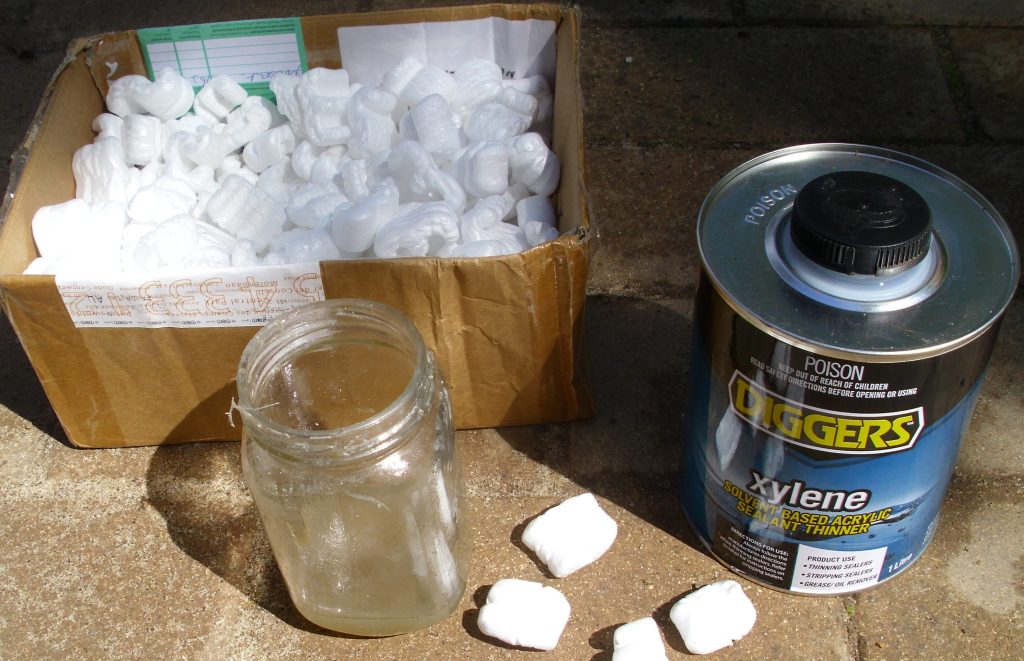
Figure 4: Making Coil Lacquer
I wound simple cylindrical shaped coil of 14 turns double spaced, and measured its Q at HF with a Q meter. I then painted the coil with my home made coil lacquer, and waited for it to dry. The Q was up to 10 points lower at 2.2 mHz and 20 points higher at 7.0 mHz.
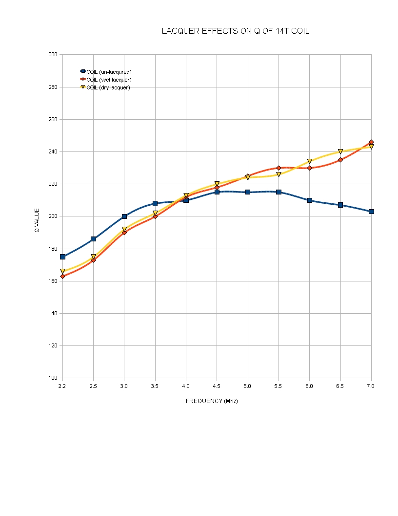
Figure 5: Coil Q (before and after)
The variations are probably due to hand capacitance, the turns moving on the loose wound coil, and measurement accuracy. I estimate the measurement error to be about 5 to 10 points. The graph shows that the coil was largely unaffected by the lacquer. The lacquer certainly was not detrimental to the Q.
Q METER
I used a HP 4342 Q meter. It is extremely easy to use. You connect the coil to the terminals on the top. It has a frequency control on the left side, that covers from 22 kHz to 70 mHz in seven ranges. You use this to excite the coil under test. I used the 2.2 to 7.0 mHz range, and measured the Q at 0.5 mHz intervals. On the right is a variable capacitor control, which covers 25 to 470 pF and you adjust this to tune for maximum reading on the meter. The meter can indicate Q values from 30 to 1000 in four ranges. You simply read the Q value from the meter, and record the readings.
MAKING A PLASTIC FORMER
I needed some sort of former, which would allow me to wind the turns on, keep the required shape, allow coil lacquer to be applied (without bonding to the former), then allow the finished coil to be removed. I wonder how they were originally manufactured? Perhaps with a three piece former, that could be reduced in size after wire winding, and then removed piece by piece, or perhaps an expanding internal mandrel. It would need a spiral grove to hold the wire in place.
The variometer required a ball shape for both the inner and outer coils. The inner and outer coils were different diameters, so two mandrels were required. I decided that only half a ball was required, as each winding was symmetrical. I also decided that one mandrel would be suitable, providing it had two different diameters.
I procured a piece of scrap wood, placed a bolt through it, tightened it in the lathe chuck. I then machined it down in size, into an approximation of the hemisphere coil with two different profiles.
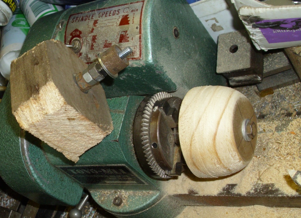
Figure 6: Making the Mandrel on a Lathe
I wound some turns on the mandrel, but they slipped off. It would require a groove, but if I cut a grove in the mandrel, the wire would stay on properly, but the lacquer would bond it to the former. On camping trips, I have boiled drinking water to purify it, then saved it in an empty PET (Poly Ethyl Terephalate) drink bottle. I discovered that pouring boiling water into a PET bottle causes it to distort and shrink. So I retrieved some bottles from the rubbish bin, cut then up, and placed them over the wooden mandrel. I then slowly and evenly heated them with a heat shrink gun. They slowly collapsed and formed a tight fit on the mandrel. I made sure that there was overlap at each end, to keep them tight on the mandrel, and so they would not slip off. When they had conformed to the mandrel shape, I cut them off.
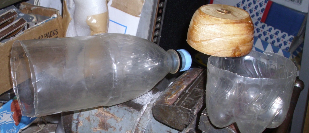
Figure 7: Cutting Plastic Bottles
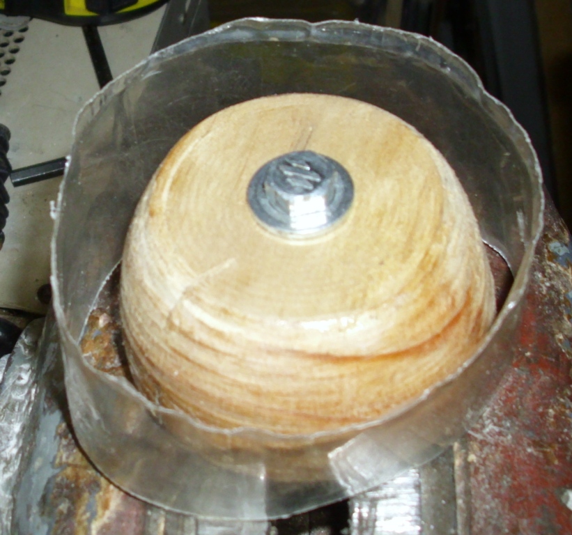
Figure 8: Before Heating
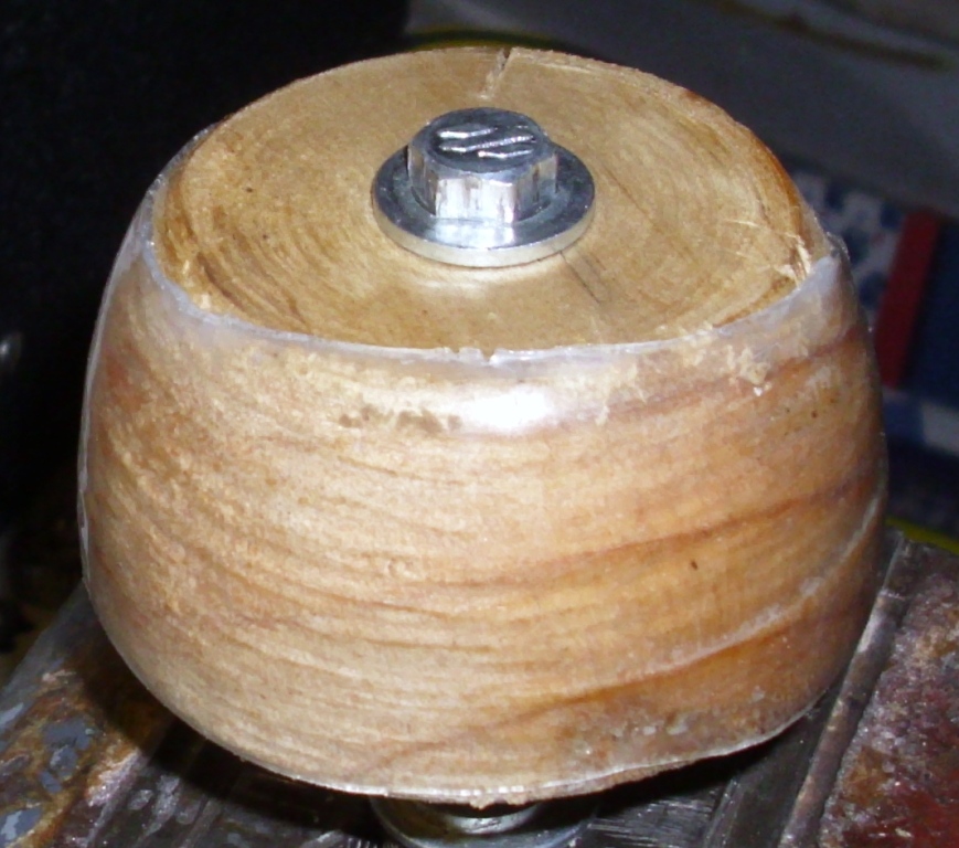
Figure 9: After heating
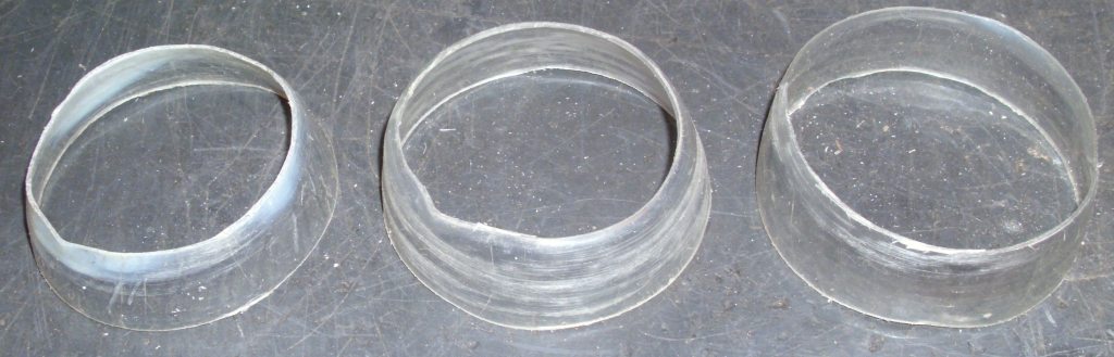
Figure 10: Several Test Formers
The formers were now the correct shape. I tried winding wire on, but it still slipped off. I made another former on the mandrel, and cut some grooves into the plastic former. It would have ideally been a spiral, with a pitch suitable for the turn spacing. I merely used the lathe to cut concentric grooves, spaced at 1 mm.
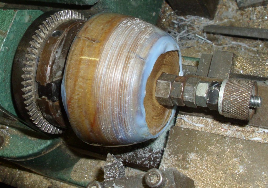
Figure 11: Former With Cut Grooves
This allowed me to wind the wire onto the former, and it did not slip off now. I merely wound a turn, and then skipped to the next groove, to achieve the turn spacing. I thought the skip would be obvious, but it was not noticeable by eye.
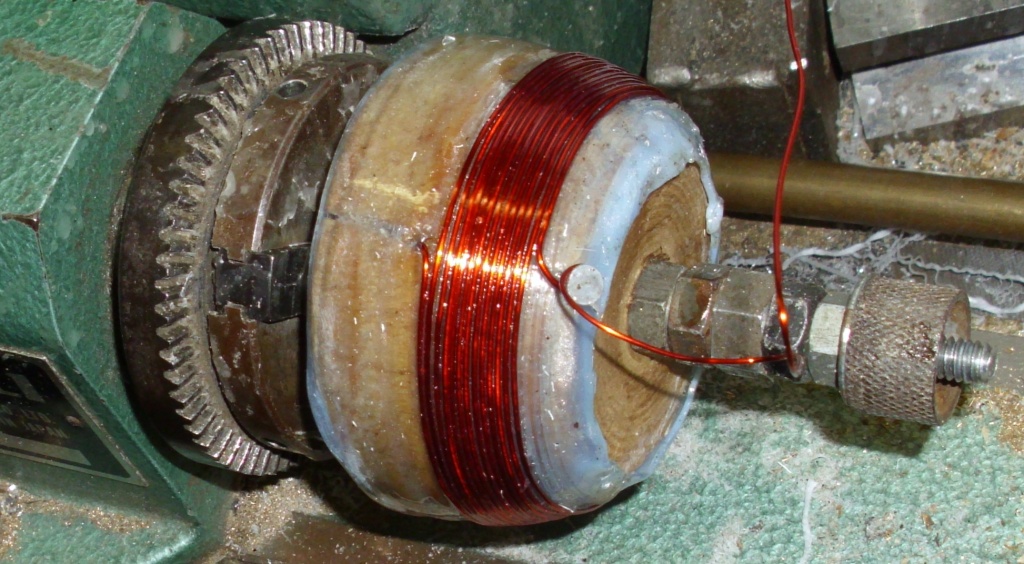
Figure 12: Double Spaced Coil Winding Using the Grooves
The winding was lacquered. The extra protruding plastic was then cut off with a hacksaw, close to the winding. A sharp knife gives a better cut edge. Always cut the small end first, as it will slip off if you do it the other way.
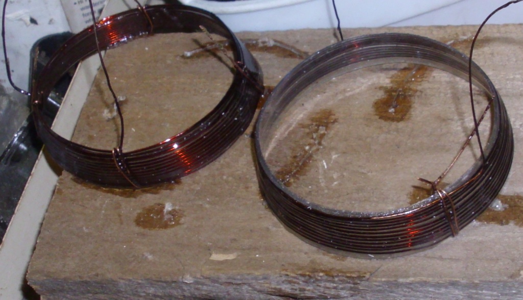
Figure 13: Original Former-less Coil (left) with a new Wound Former (right)
I compared the new coil to one of the good windings, and it was a close approximation. However, this outer winding was too thick to allow the inner coil to rotate. Also, it was not how it had been made originally. How had they done it?
The Q was measured to determine what effect the former had on the Q. The former actually increased the Q, probably because it kept the windings at a constant double spacing throughout the winding. The former-less turns were not as regular, and wandered around a little. The INNER coils had a similar curve shape on the graph. The OUTER coils had a similar curve shape on the graph. I also measured a coil from an SCR-274N Command set as a comparison. It used a ceramic former, with a molded spiral for spacing the turns, and it used very thick wire. It generally had a higher Q.
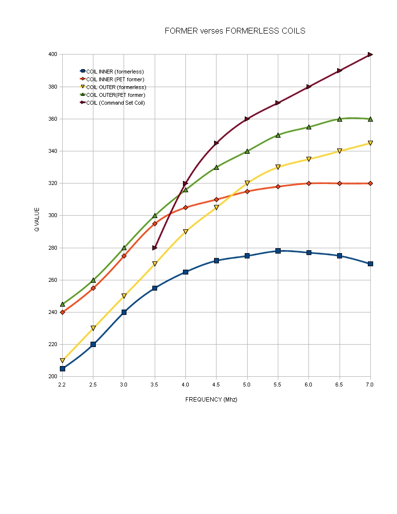
Figure 14: Comparing the Q of a Former-less Coil and a Coil with a PET Former.
MAKING A FORMER-LESS COIL
When I use glue, or fiberglass, or fill something with silicone rubber, the finish can be rough. A way to make this smooth, is to stretch clear kitchen film (sandwich wrap), over the glue/fiberglass/rubber while it is liquid, smooth out the wrinkles, and wait for it to cure. The film can then be peeled off, and a smooth finish results. Perhaps I can apply this method? I stretched some kitchen film over the wooden mandrel. I wound on some wire, but it still fell off.
Old radio books of the 1920s vintage, showed methods of winding spider coils, pancake coils and wave wound coils, using wooden spokes to guide the wire. The spokes are removed after the coil is wound and lacqured. I borrowed some dressmakers pins from the sewing basket. These were about the same diameter as the wire, so would provide the appropriate gap between turns. I drove the pins into the wooden mandrel, using a wire to keep a constant spacing. It required 4 pins per turn, so they were arranged at 90 degrees. I had to have pins for each turn and as there were 14 turns in the original coil, there were 4x14=56 pins driven into the former.
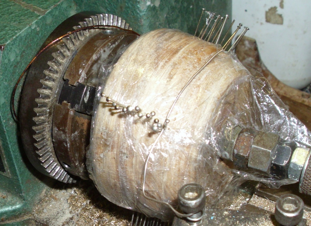
Figure 15: Mandrel With Pins
I wound on the wire, and it now stayed in place. I lacqured the coil, using 4 coats. I carefully removed the pins. I gently eased the coil off the mandrel, and removed the kitchen film from the inside, then placed a coat of lacquer on the inside. The coil held its shape.
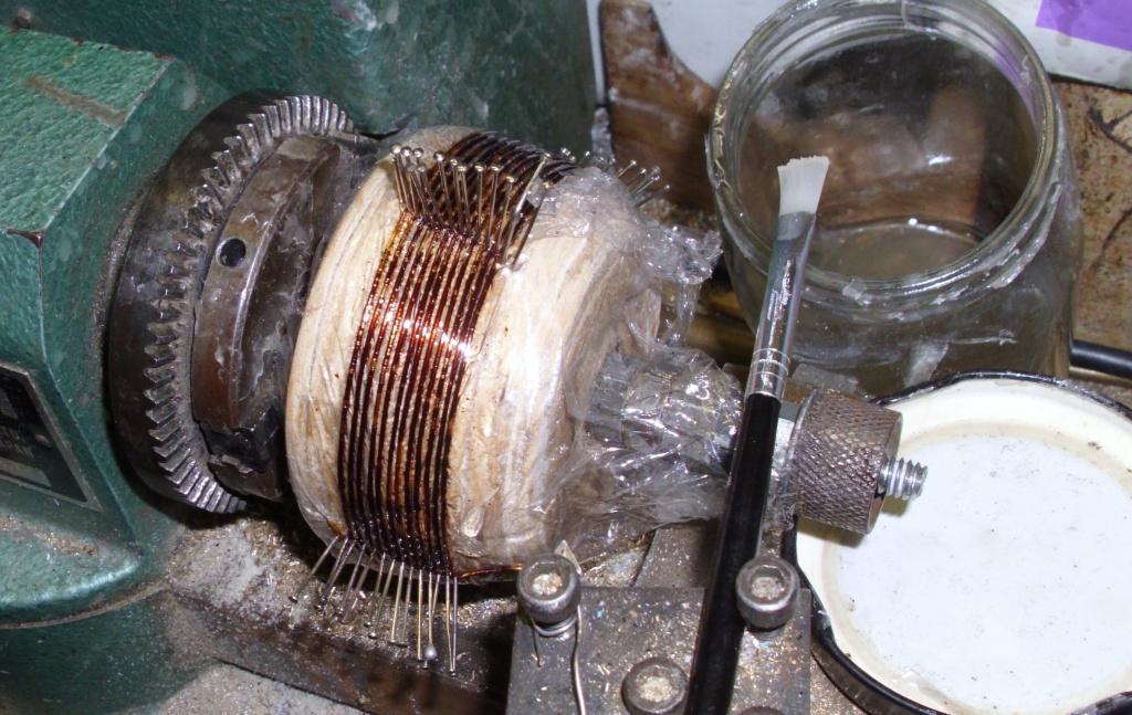
Figure 16: Finished Former-less Coil
The four coils were assembled, onto the bakelite frame. The two inner coils were attached to the rotating shaft, using the original plastic braces. They were held in place with clips, and painted with the coil lacquer, (used as glue), to hold them together. The shaft was inserted into the frame, and the end wipers attached. The outer windings had the little plastic feet attached, and held in place and glued using the same method.
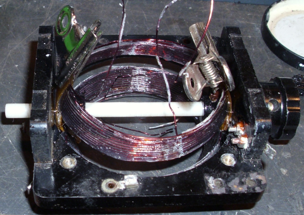
Figure 17: Assembling the Variometer using Clips
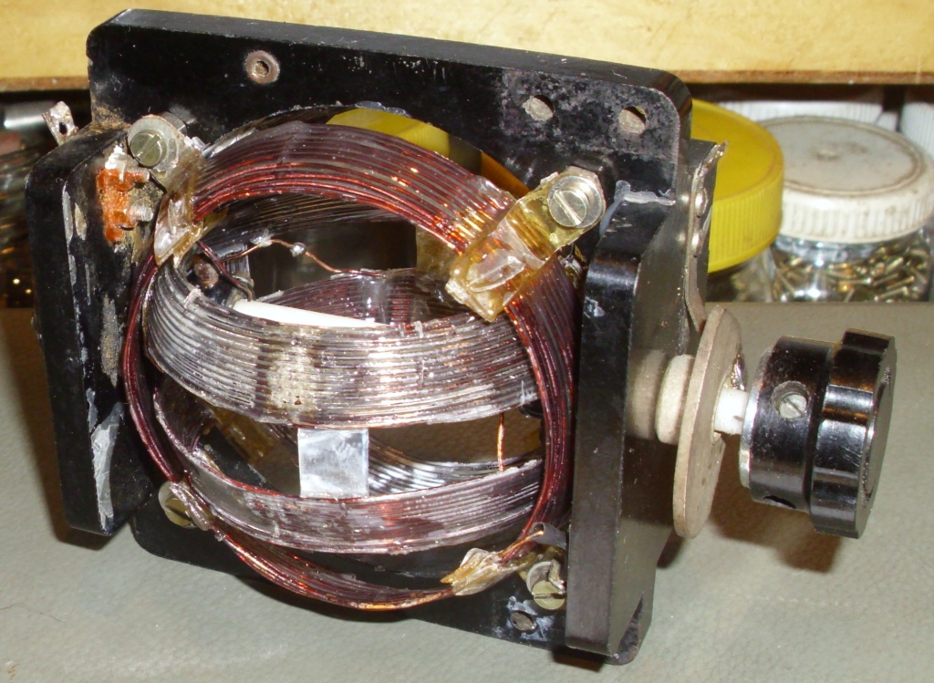
Figure 18: The Completed Variometer
The variometer was completed and mechanically, the inner coils rotated properly. The four coils were connected as per the original arrangement. How was it electrically?
TESTING
The Q of one of the outer windings was measured. The Q was different to an isolated coil, as the proximity of the other windings and the coupling lowered the Q. The Q also varied, depending on the position of the rotating coil, so it was measured under two conditions. It was measured fully meshed (0 degrees rotation) and at right angles (90 degrees rotation). It was compared to the original AWA made variometer. The new coil had a higher Q under most conditions. This may be due to the tighter coupling of the original AWA variometer (it was more accurately made), and it was measured in the Aerial Coupling unit (the coils disconnected for testing) so there may have been extra capacitance involved. I was pleased to see the curves on the graph were a similar shape, and did not have a worse Q.
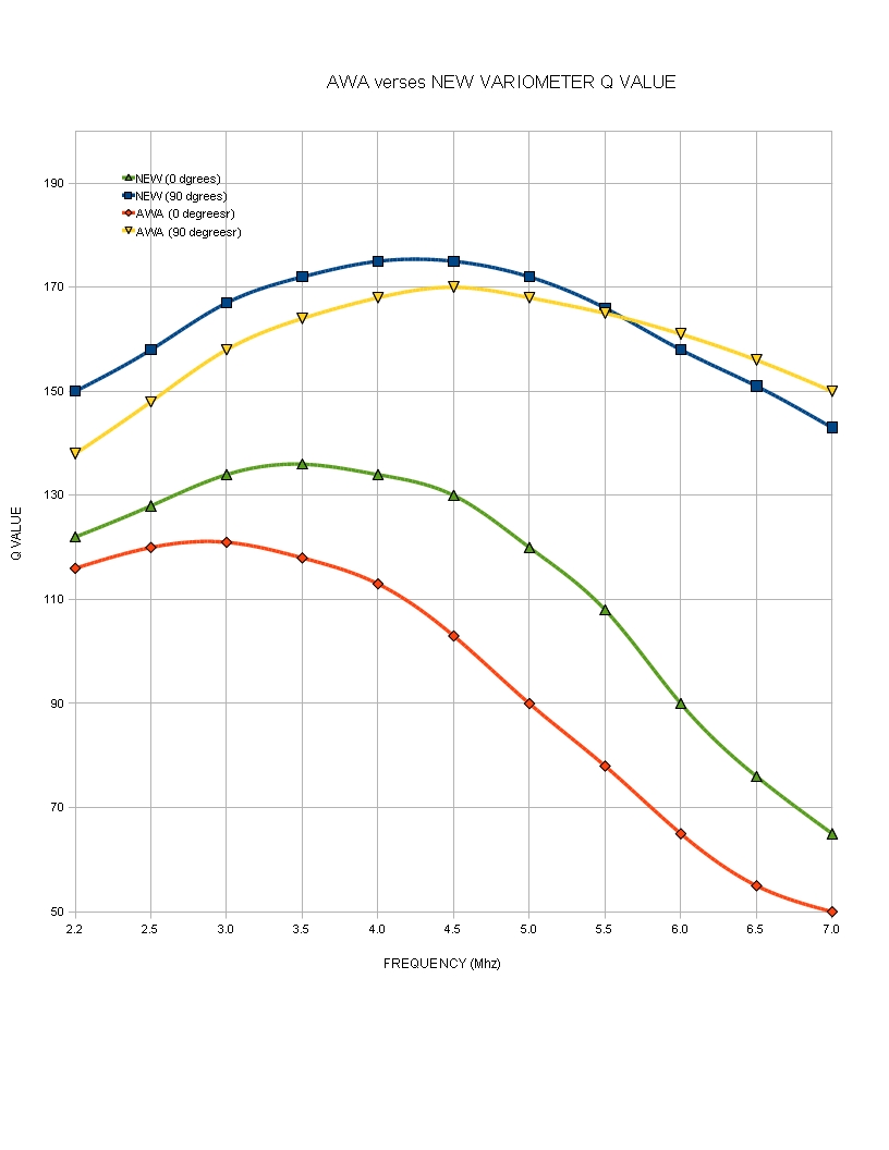
Figure 19: Variometer Q
I tested the variometer as a vari-coupler, connected as a variable transformer. The outer windings were used as the primary, and the inner windings were used as a secondary. I applied an RF signal generator to the primary and connected an oscilloscope to the secondary. There was maximum coupling when set to zero degrees rotation. There was almost zero coupling when set to 90 degrees rotation. It appeared to work well.
CONCLUSION
The unusual variometer can be repaired, and the Aerial Coupler is can be restored to a working condition. It is still unclear how the coils were originally manufactured. The method of producing a usable coil lacquer is fairly simple, and it does not reduce the Q of the coil. Coil formers of any shape can be made with a wooden mandrel and some recycled plastic bottles. Former-less coils can also be made, in any shape with any turn spacing.
Copyright
Ray Robinson