The "Command" radio is a description of the radio function, rather than a specific model. The "Command" function was to communicate between aircraft. The "Liaison" function was to communicate back to base. However, functions often become blurred in use, and even though there were several different models and generations of "Command" radios, one particular model has become popularly known as "Command sets".
The Command set is a general title for several groups of receivers and transmitters used in World War 2, which are more specifically called the (United States Army Air Force) SCR-274N, (United States Navy) ATA/ARA, and the (United States Navy) AN/ARC-5. They were used for Air to Air, Air to Ground communications and for receiving Navigation signals. They are a unique design of that era, in that most radios would use a band switch to change to a different frequency band, whereas this design selects a completely different receiver or transmitter. Here is more complete list posted by W6RIC. After the war, they were still used. I have one that was used in Australian Civil Aircraft which was reconditioned in 1956.
The Army SCR-274N series radios were available in black wrinkle paint, or natural aluminium finish. The Navy ARC-5 were in black wrinkle paint. Externally they looked identical in appearance, and only differed in colour and frequency coverage. Internally they were very similar, with only minor differences, apart from the obvious ones relating to the frequency. The SCR-274N series had BC-454 type names and the ARC-5 had R-25 and T-20 type names for the receivers and the transmitters. The adapter drawer on the front had a different knob and label for Army and Navy. Some of the low frequency receivers had a different antenna connection so that a loop aerial could be connected. The circuits were almost the same, with only a few small changes because of the frequency coverage. The valve line up was the same, except that some ARC-5 receivers used a 12SF7 second IF valve instead of the 12SK7 which was more common. Here is a list of differences compiled by Ray Mote.
They are a very nicely made radio. The metal parts are aluminium pressings, with rivets and riveted nuts. The capacitors, chokes and transformers are in cylindrical metal cans with mica insulators. The resistors are mounted on mica tag strips. The wire is a cotton covered type, sometimes with a tropical proofing. All the connectors use mica sheet. The RF coils, IF transformers, and dynamotor all plug in.
They can be operated locally, using a tuning knob and an adapter. Normally, they would be remotely controlled using a control box. The control box had electrical connections for the Gain and MCW/OFF/CW switch, and a flexible tuning shaft for the frequency.
There was a modification published in the post war magazines which
involved adding local controls and a coaxial antenna connector. This involved
drilling holes in the receiver and removing some parts. A large percentage
of the command sets available today have been modified in this way, and are
difficult to restore to their original condition. Collectors will pay considerably
less for modified sets as the original ones are more desirable.
There are seven LF and HF receivers: the R-23 (0.19-0.55 mcs), R-23A (0.19-0.55 mcs), R-148 (0.19-0.55 mcs), R-24 (0.52-1.5 mcs), R-25 (1.5-3 mcs), R-26 (3-6 mcs), and the R-27 (6-9.1 mcs). The receivers were remotely mounted and controlled, with a C-26 one receiver control box, a C-27 one receiver control box with tuning locked, a C-38 three receiver control box, all with tuning locked and a homing receiver control. When the receivers were remotely controlled, a "plug in" on the front, called an adapter, was used to enable the remote control. This adapter, the MX-21, was merely a link inside the adapter box. When the receiver was used in local control, the adapter C-24 had a volume control and ON/OFF/BFO switch. An ARC 6743 local tuning knob was used for local tuning. An MX-20 power adapter was available that had a connector on the front so that power was available for other equipment, usually an homing receiver. There was also an MX-19 audio adapter for instrument landing equipment. The receivers were mounted in racks, with several bays, the MT-7 held one receiver, the MT-63 held two receivers, the MT-65 held three receivers, and the MT-67 held four receivers. Each receiver had its own dynamotor. All receivers, and accessories, are 28 volts DC, except the R-148/ARC-5X. It is 12 volts DC, and has a MT-411/ARC-5X rack, and DY-1/ARR-2X dynamotor.
There are eight transmitters: T-15 (0.5-0.8 mcs), T-16 (0.8-1.3 mcs), T-17 (1.3-2.1 mcs), T-18 (2.1-3 mcs), T-19 (3-4 mcs), T-20 (4-5.3 mcs), T-21 (5.3-7 mcs), and the T-22 (7-9.1 mcs). The transmitters were similarly remotely mounted and controlled, with the C-29 control box, which controlled from 1 to 4 transmitters. The transmitters were mounted in racks, with several bays, the MT-69 held one transmitter, the MT-71 held two transmitters, the MT-73 held three transmitters, and the MT-75 held four transmitters. There was an RE-2 antenna changeover relay box, that also had a RF antenna current meter. The power for the transmitters came from the MD-7 modulator which also has a DY-8 dynamotor to generate the high voltage.
R-23
The R-23 is mainly used as a navigation receiver, and has 1 terminal post for the antenna, 2 terminal posts for loop operation, with a spline shaft control to switch between them, by using the C-25 remote switch. Schematic. The frequency coverage is 190-550 kcs and the Intermediate Frequency is 85 kcs. The valve line-up is: 12SK7 RF amp, 12K8 mixer, 12SK7 first IF amplifier, 12SF7 second IF amplifier, 12SR7 detector, AVC, CW oscillator, and 12A6 audio output. The R-23 and R-24 are considered Navigation receivers and have the same design and circuit diagram. The diode in the 12SF7 is not used and connected to the cathode. One diode in the 12SR7 is used as the audio detector. The other 12SR7 diode is used as the AVC rectifier, and supplies the first IF amplifier and the RF amplifier. This LF receiver, could also be fitted with 2 other adapters. It could be fitted with an MX-19 audio adapter for the Instrument Landing System (ILS). It could also be fitted with a MX-20 power adapter for supplying power to other equipment.
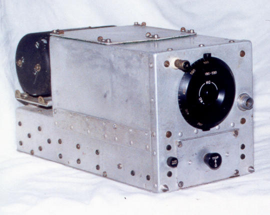
R-23A
The R-23A is mainly used as a navigation receiver, and has 1 terminal post for the antenna, 2 terminal posts for loop operation, with a spline shaft control to switch between them, by using the C-25 remote switch. The photograph shows a screw on cap for protection the spline shaft when it is not used. Schematic. The frequency coverage is 190-550 kcs and the Intermediate Frequency is 85 kcs. The valve line-up is: 12SK7 RF amplifier, 12K8 mixer, 12SK7 first IF amplifier, 12SF7 second IF amplifier, 12SR7 detector, AVC, CW oscillator, and 12A6 audio output. This R-23A is serial number 1475. The R-23A is an improved version of the R23. It has more audio power output, by using a 1k cathode resistor (instead of 1.5k) in the 12A6 audio output. It has increased coupling in the 3rd IF transformer for more audio output. The AVC circuit is improved so that it is independent of modulation depth. AVC is applied to the RF, mixer and 1st IF valves (instead of just the RF and 1st IF valves). The R-23A and R-148 are considered Navigation receivers and have the same design and circuit diagram (except the R-148 has 12V heater wiring). One diode in the 12SR7 is used as the audio detector. The other 12SR7 diode is used as the AVC rectifier, and supplies the first IF amplifier, mixer and the RF amplifier. The diode in the 12SF7 is also connected to the AVC line. This LF receiver, could also be fitted with 2 other adapters. It could be fitted with an MX-19 audio adapter for instrument landing equipment. It could also be fitted with a MX-20 power adapter for supplying power to other equipment.
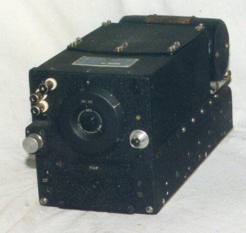
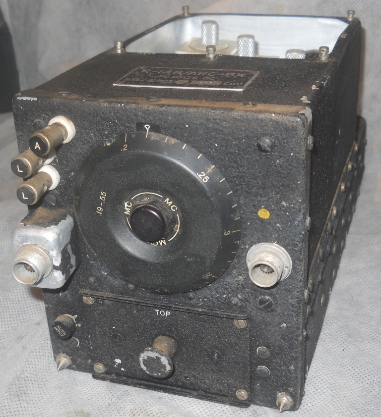
R-148
The R-148 is mainly used as a navigation receiver, and has 1 terminal post for the antenna, 2 terminal posts for loop operation, with a spline shaft control to switch between them, by using the C-25 remote switch. Schematic. The frequency coverage is 190-550 kcs and the Intermediate Frequency is 85 kcs. The valve line-up is: 12SK7 RF amplifier, 12K8 mixer, 12SK7 first IF amplifier, 12SF7 second IF amplifier, 12SR7 detector, AVC, CW oscillator, and 12A6 audio output. The R-148 is the same as the R23A, except it has 12 volt heater wiring and uses a DY-1 dynamotor running off 12 volts DC. AVC is applied to the RF, mixer and 1st IF valves (instead of just the RF and 1st IF valves). The R-23A and R-148 are considered Navigation receivers and have the same design and circuit diagram (except the R-148 has 12V heater wiring). One diode in the 12SR7 is used as the audio detector. The other 12SR7 diode is used as the AVC rectifier, and supplies the first IF amplifier, mixer and the RF amplifier. The diode in the 12SF7 is also connected to the AVC line. This LF receiver, could also be fitted with 2 other adapters. It could be fitted with an MX-19 audio adapter for instrument landing equipment. It could also be fitted with a MX-20 power adapter for supplying power to other equipment.
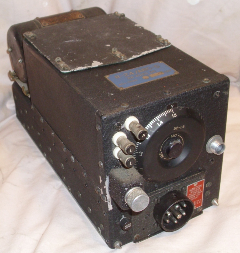
R-24
The R-24 is mainly used as a navigation receiver, and has 1 terminal post for the antenna, 2 terminal posts for loop operation, with a spline shaft control to switch between them, by using the C-25 remote switch. Schematic. The frequency coverage is 520 - 1500 kcs and the Intermediate Frequency is 239 kcs. The tube lineup is: 12SK7 RF amplifier, 12K8 mixer, 12SK7 first IF amplifier, 12SF7 second IF amplifier, 12SR7 detector, AVC, CW oscillator, and 12A6 audio output. The R-23 and R-24 are considered Navigation receivers and have the same design and circuit diagram. The diode in the 12SF7 is not used and connected to the cathode. One diode in the 12SR7 is used as the audio detector. The other 12SR7 diode is used as the AVC rectifier, and supplies the first IF amplifier and the RF amplifier. This LF receiver, could also be fitted with 2 other adapters. It could be fitted with an MX-19 audio adapter for instrument landing equipment. It could also be fitted with a MX-20 power adapter for supplying power to other equipment.
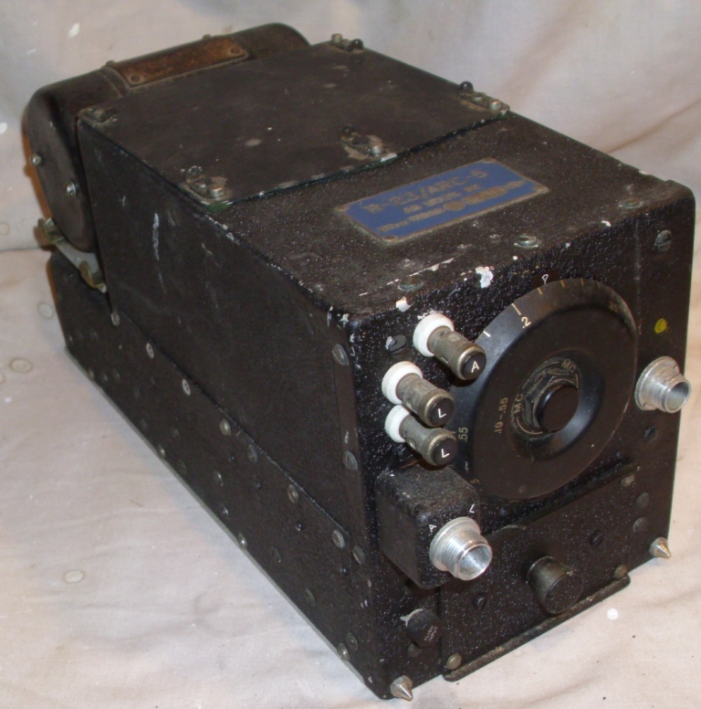
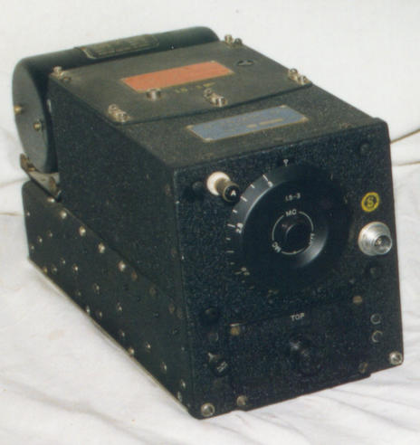
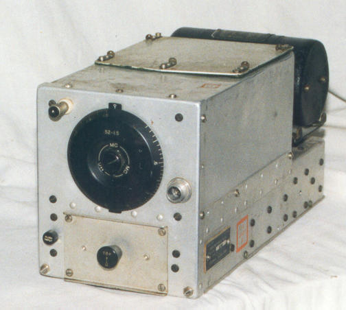
R-25
The R-25 is mainly used as a communications receiver, and has 1 terminal post for the antenna. The frequency coverage is 1.5 - 3 mcs and the Intermediate Frequency is 705 kcs. The valve line-up is: 12SK7 RF amp, 12K8 mixer, 12SK7 first IF amp, 12SF7 second IF amp and AVC rectifier, 12SR7 detector, CW oscillator, and 12A6 audio output. The one in the photograph has the "stabilised" stamp, and is serial number 3152. The valve cover (with the red plate) has a small dial underneath it for fitting to a C-26 single receiver control box. The R-25, R-26, and R-27, are all classed as communications receivers and use the same circuit design and diagram. The 12SF7 diode provides the AVC, which is applied to the first IF amplifier, and RF amplifier. The 12SR7 diode is used as the audio detector. The other 12SR7 diode is not connected. Schematic.
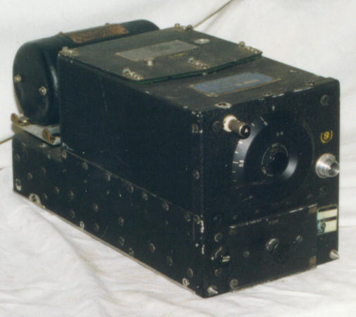
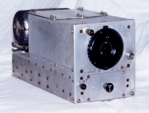
R-26
The R-26 is mainly used as a communications receiver, and has 1 terminal post for the antenna. The frequency coverage: 3.0-6.0 mcs and the Intermediate Frequency is 1415 kcs. The tube lineup is: 12SK7 RF amplifier, 12K8 mixer, 12SK7 first IF amplifier, 12SF7 second IF amplifier and AVC rectifier, 12SR7 detector, CW oscillator, and 12A6 audio output. This one has serial number 1182 and has the stabilised stamp. The R-25, R-26, and R-27, are all classed as communications receivers and use the same circuit design and diagram. The 12SF7 diode provides the AVC, which is applied to the first IF amplifier, and RF amplifier. The 12SR7 diode is used as the audio detector. The other 12SR7 diode has a capacitor connected to ground. Schematic.
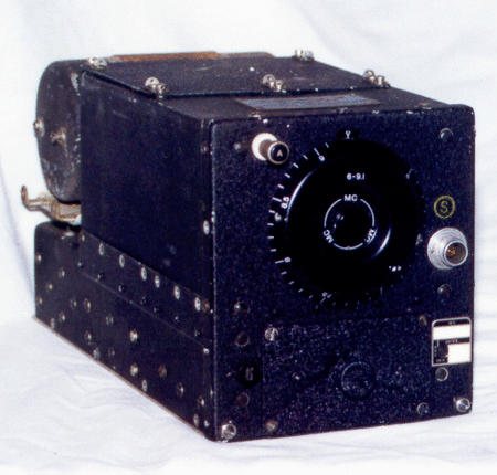
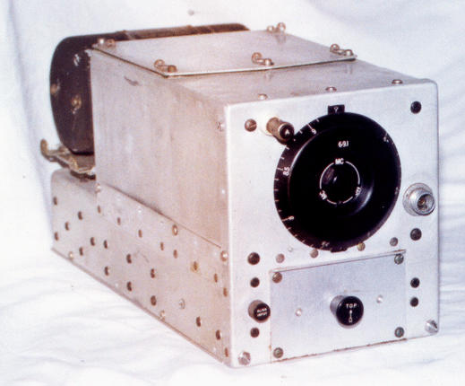
R-27
The R-27 is mainly used as a communications receiver, and has 1 terminal post for the antenna. The frequency coverage: 6.0-9.1 mcs and the Intermediate Frequency is 2830 kcs. The tube lineup is: 12SK7 RF amplifier, 12K8 mixer, 12SK7 first IF amplifier, 12SF7 second IF amplifier and AVC, 12SR7 detector, CW oscillator, and 12A6 audio output. Serial number 6192. It has the S stamp on the front to indicate a "Stabilised" unit. The paint is in very good condition. The R-25, R-26, and R-27, are all classed as communications receivers and use the same circuit design and diagram. The 12SF7 diode provides the AVC, which is applied to the first IF amplifier, and RF amplifier. The 12SR7 diode is used as the audio detector. The other 12SR7 diode is connected to ground. Schematic.
There are four receivers: the BC-453 (0.19-0.55 mcs), BC-946 (0.52-1.5 mcs), BC-454 (3-6 mcs), and the BC-455 (6-9.1 mcs). The receivers were remotely mounted and controlled, with a BC-473 one receiver control box, a BC-496 two receiver control box, or a BC-450 three receiver control box. Each receiver had its own dynamotor. The receivers were mounted in racks, with several bays, the FT-233 held one receiver, the FT-227 held two receivers, the FT-220 held three receivers, and the FT-264 held four receivers. When the receivers were remotely controlled, a plug in on the front, called an adapter was used to enable the remote control. This adapter, the FT-230, was merely a link inside the box. When the receiver was used in local control, the adapter FT-260 had a volume control and ON/OFF/BFO switch. An MC-237 local tuning knob was used for local tuning. An FT-310 adapter was available that had a connector on the front so that power was available for other equipment. The BC-946 usually had this type of adapter.
There are four transmitters: BC-696 (3-4 mcs), BC-457 (4-5.3 mcs), BC-458 (5.3-7 mcs), and the BC-459 (7-9.1 mcs). The transmitters were similarly remotely mounted and controlled, with the BC-451 control box, which controlled from 1 to 4 transmitters. The transmitters were mounted in racks, with several bays, the FT-234 held one transmitter, the FT-226 held two transmitters, the FT-276 held three transmitters, and the FT-331 held four transmitters. There was a BC-442 antenna changeover relay box, that also had a RF antenna current meter. The power for the transmitters came from the BC-456 modulator which also has a DM-33 dynamotor to generate the high voltage. The handheld microphone used was a T-17.
BC-453
Frequency coverage: 190-550 kcs Intermediate Frequency: 85 kcs Valves: 12SK7 (VT131) RF amp, 12K8 (VT132) mixer, 12SK7 (VT131) first IF amp, 12SK7 (VT131) second IF amp, 12SR7 (VT133) detector and CW oscillator, 12A6 (VT134) audio output. This example was made by Western Electric serial number 68444. Schematic.
BC-946
This was a later addition to the receiver range, and that is why the BC number is much higher. Frequency coverage: 0.5-1.5 mcs Intermediate Frequency: 705 kcs Valves: 12SK7 (VT131) RF amp, 12K8 (VT132) mixer, 12SK7 (VT131) first IF amp, 12SK7 (VT131) second IF amp, 12SR7 (VT133) detector and CW oscillator, 12A6 (VT134) audio output. This one is shown with an FT-230 remote control adapter. It was normal to have an FT-310 power adapter fitted for supplying power to a homing receiver. This set is made by Colonial Radio serial number 5393. Schematic.
BC-454
Frequency coverage: 3.0-6.0 mcs Intermediate Frequency: 1415 kcs Valves: 12SK7 (VT131) RF amp, 12K8 (VT132) mixer, 12SK7 (VT131) first IF amp, 12SK7 (VT131) second IF amp, 12SR7 (VT133) detector and CW oscillator, 12A6 (VT134) audio output. This example was made by Colonial Radio serial number 4718. Schematic.
BC-455
Frequency coverage: 6.0-9.1 mcs Intermediate Frequency: 2830 kcs Valves: 12SK7 (VT131) RF amp, 12K8 (VT132) mixer, 12SK7 (VT131) first IF amp, 12SK7 (VT131) second IF amp, 12SR7 (VT133) detector and CW oscillator, 12A6 (VT134) audio output. This example was made by Colonial Radio serial number 1480. It is shown with an FT-230 remote control adapter. Schematic.
SBA RECEIVER
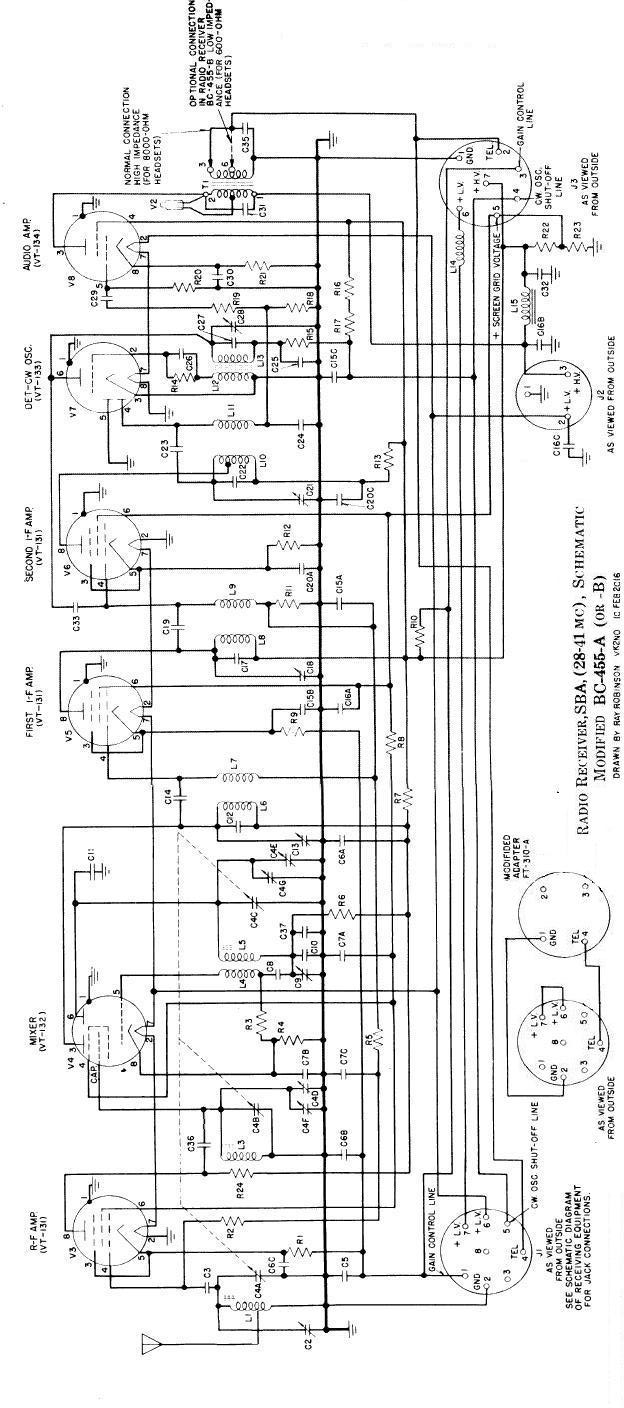
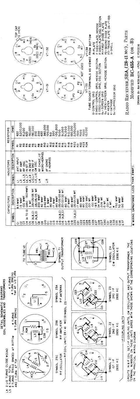
When the USAAF arrived in England, and took over many British airfields, they had no receivers capable of Standard Beam Approach (SBA) landings. This was the Lorenz system, which projected two beams down the runway, transmitting on 33 Mhz. It used the morse letter A (dit dah) for the left beam, and the morse letter N (dah dit) for the right beam. In the middle, these overlapped to form the steady tone. A pilot could listen to these beams on landing approach, and fly to the left or right, until a steady tone was heard. A 30-40 MC receiver was built in England by Eighth Airforce radiomen, from a BC-455 command set. Frequency coverage: 28-41 mcs Intermediate Frequency: 2830 kcs Valves: 12SK7 (VT131) RF amp, 12K8 (VT132) mixer, 12SJ7 (VT162) first IF amp, 12SK7 (VT131) second IF amp, 12SR7 (VT133) detector and CW oscillator, 12A6 (VT134) audio output. It used an FT-310 remote control adapter containing a 4 pin Type W connector. Schematic.

I-84B RECEIVER TEST SET
This is a test unit for bench testing SCR-274N receivers. It has a meter
with a select switch that can measure 5 parameters in the receiver.
The switch selects Input Voltage, Input Current, Screen Voltage, Plate
Voltage, and Cathode Current. The meter scale only has one set of calibration
marks and most readings are mid-scale for normal conditions. It also has
a built in remote control function, similar to the normal remote control
box. It has a CW/OFF/MCW switch, and a Gain control. There is a phone jack
for speaker, headphone, or output meter connection. One plug is for 28 VDC
input, the other connects to the receiver, rear connector. There is also
a fuse. This unit has serial number 736. It is brand new and came in
its original cardboard box. The I-84A test set has the same functions, except
it has 5 separate meters and no select switch.
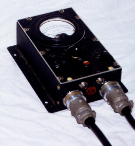
I had to modify some Utilux connectors to fit, and you can see the bright ferrules in the photograph. I turned these up on a small lathe. Connectors are always difficult to find. I have used black cable on this unit. Some connectors have an open style rear shell, and the wires exit individually. The original wire was a cotton covered type or white, and was usually laced into a cable form.
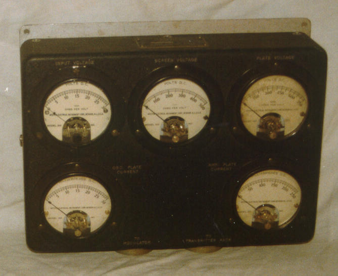
I-85A TRANSMITTER TEST SET
This is a test unit for bench testing SCR-274N transmitters. It consists of a box with 5 meters in which monitor the transmitter parameters. The test set is placed between the transmitter and the modulator. The meters show the Input Voltage (0-30v), Oscillator Plate Current (0-30ma), Screen Voltage (0-500v), Plate Voltage (0-750v) and Amplifier Plate Current (0-250ma). The I-85B test set only has one meter and a switch to select the range. When I got this test set, it was missing the top left hand meter which is used for measuring the input voltage. I made a new one from 3 meters of the same type. One provided the case to match the others, one provided the movement, and the other provided the scale.
M52215 MODULATOR TEST SET
The Modulator Test Set is a small grey box that contains a meter and 2 switches, which are used for testing the functions of the BC-456 modulator.
The test box has 2 cables with plugs that connect to the modulator. One cable connects to the modulator output socket (normally connected to the transmitter), and the second cable connects to the modulator control socket (normally connected to the transmitter control box). These cables power the modulator and connect to the various modulator parts for monitoring voltages and levels. There is a main power connector for the 28 volt input, and 3 terminals to connect an audio input source. There are 2 switches for selecting the functions to be tested. The meter is calibrated with a single scale that reads 0 to 10. There is also a phone jack for listening to the modulator output. The test set is marked serial number 7.
I have looked in the SCR-274N and AN/ARC-5 manuals that I have, and there is no mention of any modulator test set, only the receiver and transmitter test sets. The A.W.A. manual on the SCR-274N has no information on any test sets at all. This test set must be an Australian design and manufacture. It is made by A.W.A. (Amalgamated Wireless Australia) and the components and construction are consistent with their practices.
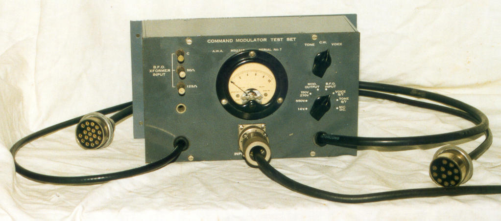
There are 2 main control switches. The emission switch at the top right hand side selects TONE/CW/VOICE which performs the same function as the switch on the transmitter control box. The function switch on the lower right hand side selects the various functions to be tested. Several switch positions act as a volt meter, and the other positions use an internal bridge rectifier and the meter acts as a level meter. The terminals on the left hand side are for connection to an audio signal generator, which has a transformer output. The microphone DC goes through this. The input terminals are labelled BFO which is the name that A.W.A. used for their audio signal generator in the 1940s.
The first position of the function switch, is labelled 14V. This measures the input voltage to the modulator, and reads 4 for 14 volts input and 8 for 28 volts input. The test set can therefore test 14 or 28 volt modulators. The second switch position is labelled 550V and measures the high voltage output from the dynamotor. The meter reads 5.5 for 550 volts output. The third switch position is labelled 270/150V and measures the low voltage output. When the emission switch is set to TONE or VOICE, the regulator in the modulator is switched on, and the voltage drops to 150 volts. The meter reads 8 for 270 volts and 4 for 150 volts. The fourth switch position labelled MOD. OUT and measures the level of audio output from the modulator. The meter reads 3 for TONE, 2 for CW, and 1 for VOICE. The fifth switch position labelled BFO is used to measure and set the input level from the signal generator. This only reads 1 at maximum output from the BFO (which seems low, and the modulator output is low as well). The sixth switch position is labelled VOICE S.T. and measures the level of the audio tone that is sent to the receiver as a side tone. (A "side tone" is some of the transmit audio that is sent to the receiver, so you can hear what you are transmitting). The meter reads 10 for TONE, 0 for CW, and 3 for VOICE. The seventh switch position is labelled TONE S.T. and measures the level of the audio tone that is sent to the receiver as a side tone. The meter reads 8 for TONE, 8 for CW, and 0 for VOICE. The eighth switch position is labelled MIC DC and measures the microphone power supply voltage. The meter indicates 3 in this position.
When I found this unit at a junk sale, it had no box or cables, but was in reasonable condition. I made a box similar in style to the other command test sets, which have a rear flange for wall mounting. I painted the box the same grey as the front panel. I then traced the circuit, and made some guesses about the modulator connections. The meter is slightly too large and covers part of the front panel engraving, but it looks original. I added the cables and connectors, checked all the components, and then applied power. The test set worked fine. The BFO input terminals were disconnected inside. I have reconnected them, but may not have it quite right, as the input levels are low. I cannot find any data or circuits for this test set.
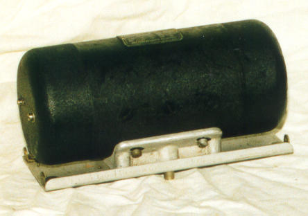
DM-32 RECEIVER DYNAMOTOR
The command sets have a small dynamotor that sits on the back deck of the receiver. It takes 28 VDC (there was a 12 VDC version) and generates 250 VDC for the valves. It has a 3 pin connector under it, so that it can be unplugged for maintenance. It sits on 4 rubber mounts, to reduce vibration. These mounts are usually removed from the receivers and they are hard to find. The dynamotors can have labels of DM-32 for the SCR-274N sets, or DY-2A/ARR-2 for the ARC-5 (and ARR-2) sets.
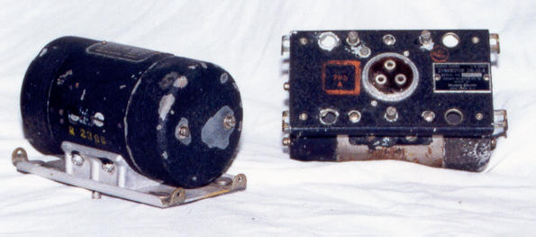
DM-33 TRANSMITTER DYNAMOTOR
The transmitters use one dynamotor for their High Tension supply. It is continuously rated at 575 volts dc at 160 ma. They only need one, as only one transmitter is on at a time. The dynamotor is located on the BC-456 modulator.
REFERENCES
The Command Set Story, Gordon Elliot White, CQ, November 1964, P37-40.
Command Sets, Gordon Elliot White, CQ, October 1965, P34-37.
Command Sets, CQ, Cowan Publishing Corp, 1957, Library of Congress 58-59924.
Electric Radio In Uniform, Command Sets Part I, Walt Hutchens, Electric Radio, Number 11, P4-7,20-24.
Electric Radio In Uniform, Command Sets Part II, Walt Hutchens, Electric Radio, Number 12, P4-7, 26-29.
On the Air with the Command Set Triplets, Jim Hanlon, Electric Radio, Number 74, P4-9, 39.
On the Air with the Command Set Transmitters, Jim Hanlon, Electric Radio, Number 75, P4-9, 38.
Instruction Book for OPERATION AND MAINTENANCE of RADIO SET SCR-274-N, February 15 1943
AN 08-5Q-95 Handbook of OPERATING INSTRUCTIONS for MODEL AN/ARC-5 Aircraft Radio Equipment, 21 February 1944
AN 16-30ARC5-2 Handbook of MAINTENANCE INSTRUCTIONS for MODEL AN/ARC-5 Aircraft Radio Equipment VOLUME 1 LF MF HF Components, 23 February 1944, Revised 15 june 1945
AN 08-10-195 Handbook of MAINTENANCE INSTRUCTIONS for MODEL AN/ARC-5
Aircraft Radio Equipment VOLUME 2 VHF Components, 15 April 1944
COMPLETE LIST OF COMMAND SETS
COMMAND SET DIFFERENCES
R23 R24 Schematic
R23A Schematic
R25 R26 R27 Schematic
BC-453 Schematic
BC-946 Schematic
BC-454 Schematic
BC-455 Schematic
SBA Schematic
SBA parts list