
Picture 1: The Lorenz Beam showing dit and dah and overlap (source Wiki)
INTRODUCTION
During the 1930s and 1940s a Standard Beam Approach (SBA) receiver was used by aircraft, to land when visual conditions were poor (due to rain, low cloud, or fog). It was a navigation receiver, and allowed the pilot to line the aircraft up on the runway when preparing in to land.
The most important pre-war Navigation Aid (navaid) was the Lorenz Radio Range, developed in Germany as a Blind Landing System (BLS), and was used extensively in Europe. It was developed starting in 1932 by Dr. Ernst Kramar of the Lorenz company. It was adopted by Lufthansa in 1934 and installed around the world. Lorenz used a 33.33 MHz radio transmitter, which projected two overlapping beams down the runway. The beams were switched on and off alternately, the left beam creating dits (morse letter E), the right beam creating dahs (morse letter T). Where the beams overlapped along the runway centre line, a continuous tone was heard. On approach, when the pilot heard dits, he turned right until he heard the steady tone. Similarly if he heard dahs, he turned left. This was an aural navigation method. The pilot had to listen to the tones in his earphones and fly accordingly.
Picture 1: The Lorenz Beam showing dit and dah and overlap (source Wiki)
The Lorenz system was installed at many British airfields and called Standard Beam Approach (SBA). It used the morse letter A (dit dah) for the left beam, and the morse letter N (dah dit) for the right beam. In the middle, these overlapped to form the steady tone. When the USAAF arrived in England, and took over many British airfields, they had no receivers capable of SBA landings. Eighth Bomber Command would not fly missions if the ceiling for the return flight was expected to be less than 500 feet. They ordered several thousand sets in 1942, but they were never built. A design proposal for such a receiver was sent to the USA but the project was killed in Washington. A 30-40 MC receiver was built in England from a BC-455 command set, by Eighth Airforce radiomen, to receive the British instrument landing signals. (White)
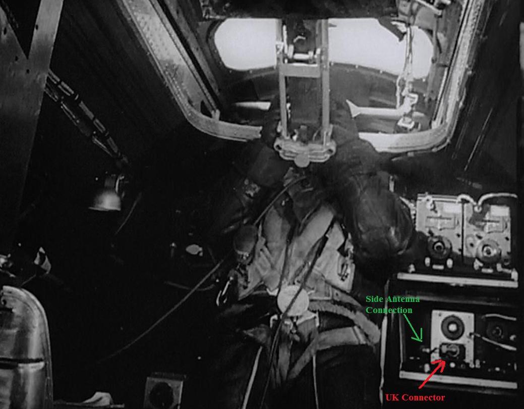
Picture 2: B-17 Gunner and SBA Receiver, Schweinfurt raid. (photo from DS)
The Instrument Landing System (ILS) began to replace the SBA system after January 1944, and was used by the Eighth and Ninth Airforces and the RAF. It was similar to the SBA system, but had a meter on the aircraft instrument panel to indicate left or right.
DESCRIPTION
This particular radio was modified in World War II to allow American aircraft to land at English airfields after their missions. The original receiver (before modification), was the BC-455 from the American SCR-274N group of radio receivers. It is a super-heterodyne receiver, single band, remotely controlled, continuously tunable, and uses octal valves. It has an RF amplifier using a VT-131 (12SK7), a mixer using a VT-132 (12K8), two IF amplifiers using two VT-131 (12SK7), a BFO/DETECTOR using a VT-133 (12SR7), and an AF amplifier using aVT-134 (12A6). The frequency coverage is 6 to 9 Mhz and the IF frequency is 2830 Khz. It has a small dynamotor that provides 250 volts DC.
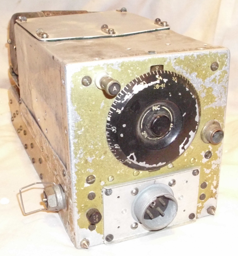
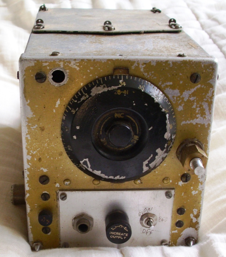
Picture 3: SBA RECEIVER
The SBA modifications were changes to the receiver frequency, antenna input, and audio output. This SBA receiver looks the same as a BC-455, but with three visible external differences. There is a PYE antenna socket on the left hand side, a Type W connector in the front adapter, and the dial is engraved with the frequency from 28 to 41 MC. The receiver plugs into a normal FT-233 single receiver rack, and uses a normal remote control box, (probably a BC-473) with Bowden cable frequency tuning.
CONTROLS
There are few controls actually on the receiver, as it is intended for remote operation. The only local control is the antenna trimmer capacitor, labeled ALIGN INPUT, which is set once for the frequency in use. The BFO note tuning is set by a recessed screw on the side. The remote control box has an RF gain control, labeled INCREASE OUTPUT, two headphone jacks, labeled A-TEL and B-TEL, a headphone switch that can select one of the two audio lines, and a CW-OFF-MCW switch, which combines the ON/OFF switch and the BFO switch. There is also a dial and a crank to tune the receiver, by using a Bowden cable, labeled TUNING.
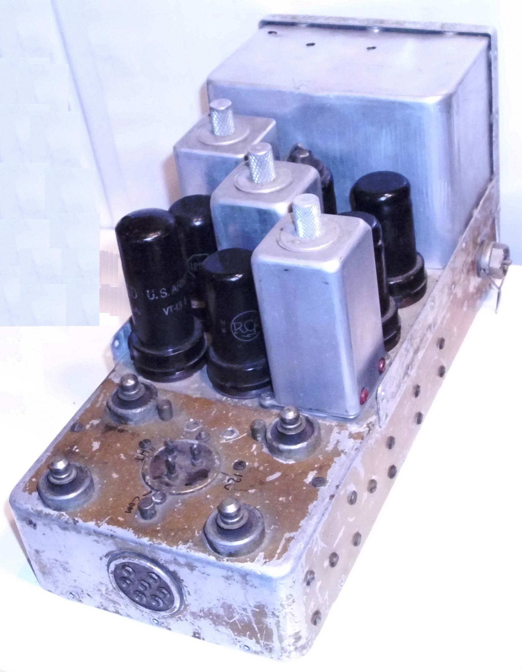
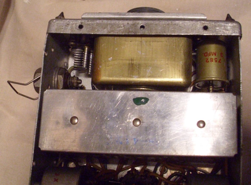
Picture 4: Radio Top view
MECHANICAL
The radio is made from precision stamped aluminium parts, assembled with rivets and riveted nuts for screws, and is very modular. The covers, and chassis are very nicely made. The IF transformers, coil box, remote control adapter, and dynamotor, can all be unplugged and changed. The connectors are mica sheet with small banana pins and sockets riveted on. The capacitors, chokes and transformers are in cylindrical metal cans with mica insulators. The resistors are mounted on mica tag strips. Note that the resistors have no outer insulation, so touching the resistor body with your finger, may result in a shock. The wire is a cotton covered type single strand, sometimes with a tropical proofing. The radio itself, plugs into a rack, and it can be changed as well.
This receiver has been painted with tropic proofing, and a lot of it has been scratched or chipped off. I did not attempt to clean it or re-paint it. A small area, where the nameplate was, had been cleaned with a solvent, and hand written numbers had been added. The numbers are: R.15?? SER. No. AW1174. The coil box has handwritten 28-41 (the frequency) and additionally is stamped 28-41MC. The IF transformers have a green dot, as does the coil box. All the coils and the IF transformers for the BC-455 had a green dot code. There is a red Signal Corps stamp as well.
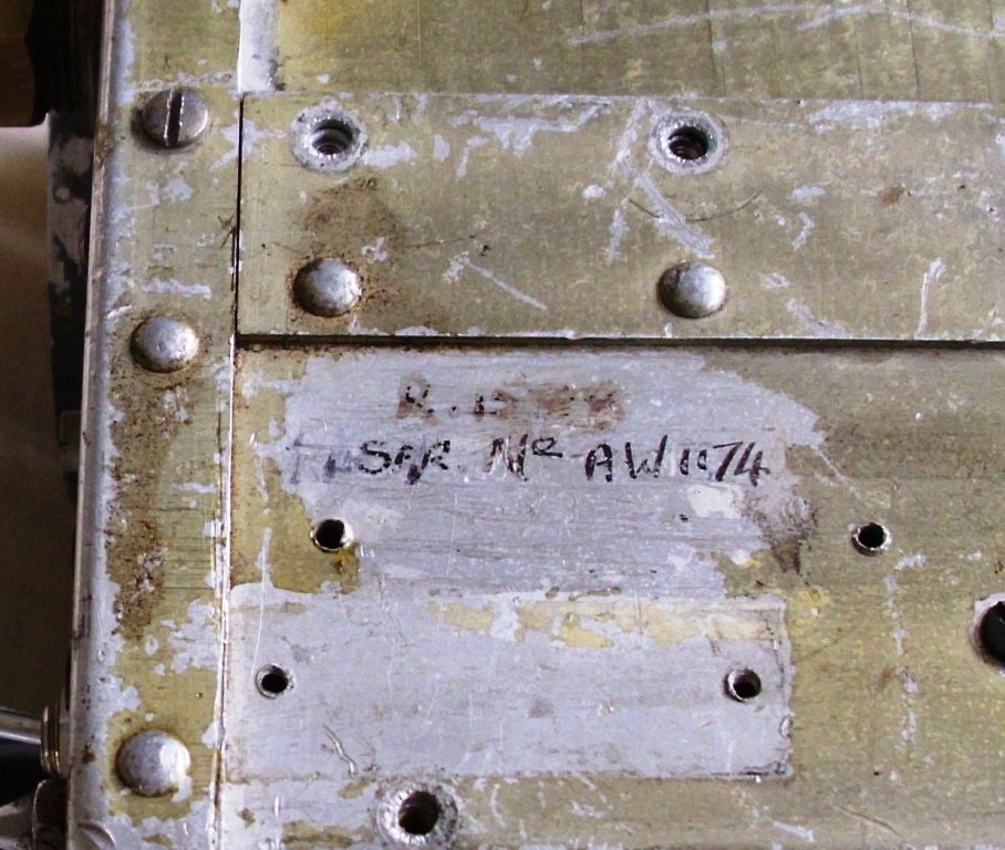
Picture 5: Nameplate

Picture 6: Nameplate from the Web Auction
I saw a similar receiver on the web auction site in 2015. Its nameplate was also removed, and handwritten in black ink on the side was R. 1598, 10D777116, SER.No. 434. There was a Signal Corps orange stamp, covered by a white stencil R and a sticker EMIS 376. It also had IF transformers with green dots, with mixed dust caps on the IF transformers, the 1st and 3rd were bakelite, and the 2nd was metal.
![]()
Picture 7: Underneath
SBA MODIFICATIONS
The modifications to convert the BC-455 to an SBA receiver were minimal. The coil box was changed for one that covered 28-41 Mhz. A padder capacitor was added to the oscillator. The top front panel antenna terminal was disconnected. A new antenna co-axial socket was mounted on the left hand side of the receiver. The antenna wiring was connected to this, and the neon protector was removed. The dial was changed to one that had 28-41 MC markings. The nameplate was removed, and some hand written numbers were added. The front FT-310 adapter was changed for one with a 4 pin Type W connector.
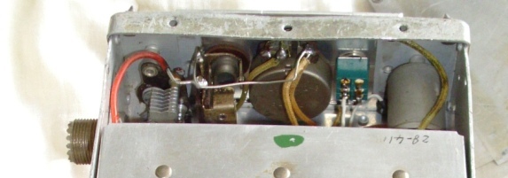
Picture 8: Coax connections
HAM MODIFICATIONS
There was a modification published in the post war magazines, which suggested adding local controls and a coaxial antenna connector. This involved drilling holes in the receiver and removing some parts. A method of adding a tuning knob was offered, using a thin brass tube pushed over the tuning spline to hold a knob. The rear connector was removed and an octal socket installed. A large percentage of the command sets available today have been modified in this way, and they are difficult to restore to their original condition. The un-modified receivers are valuable, whereas modified receivers are usually worth little money. There was a local control adapter called a FT-260-A, which provided all the controls, but these are hard to find. There was also a local control knob called an MC-237-A, and these are also hard to find. The radio has handwriting on the back shelf, identifying the dynamotor pins.
Picture 9: Ham Modifications
Picture 10: Ham Modifications
RESTORATION
Unfortunately, this receiver had the Ham modifications. Normally, I would not restore a Ham modified BC-455 receiver. However, this was the very un-common SBA receiver, so an attempt was made. The problem then became, to identify which modifications were the Ham modifications (and remove them) and which were the SBA modifications (and keep them). Some were obvious, others were doubtful, a few I had to guess.
A BC-455 receiver was placed next to the SBA receiver on the bench, and both receivers were restored at the same time, so that a comparison could be done. I had another scrap chassis to use for any parts that I needed. A circuit and a wiring diagram were printed on paper, and each wire and component was checked in both receivers, and then marked of in red pen on the diagrams. This procedure worked so well, that the SBA receiver worked at first power on. The BC-455 also worked, but the BFO was not oscillating, as a wire which had tested continuous, had afterwards broken during the restoration.
The local control modifications were removed. An original adapter receptical was installed and wired up. An FT-310 adapter was fitted with a 4 pin connector, and a guess made at the wiring. It was plugged in. Thank you to DS for providing these parts.
The SO-239 connector on the side, was removed and English PYE connector was installed, and wired. This was probably a Ham modification, as period photographs show the English connector. The missing antenna terminal was added, but not wired. A shadow on the tropic proofing, showed that there had been a terminal present when the receiver was originally painted. The removal was probably a Ham modification, as period photographs show the antenna terminal present. The antenna neon voltage protector was not there, but I did not add one. The antenna trimmer had not been modified. It was still connected. The nameplate figures and hand numbering on the side was not touched. The scratched dial was not touched. The scratched tropic proofing paint was not touched.
Several modern resistors were removed and replaced with the correct period type. All resistors were checked. The only doubtful one was the AF valve grid resistor. It should be 2 meg ohms, but an old (not modern) 1 meg ohm was fitted. It may have been correct, as it is same style and vintage as those inside the coil box. Was this an SBA mod? I fitted the correct 2 meg ohm resistor anyway.
Several modern capacitors were removed and replaced with the correct period type. All capacitors were checked. The capacitors are in sealed round cans. Many people re-stuff them with new capacitors, and then re-seal the cans. They look period but perform like modern capacitors. I chose not to do this in these two receivers, but I did use a HT voltage of only 100 volts DC, not the correct 250 volts DC. This was on the bench with an adjustable power supply. What will happen when I plug in the dynamotor, and apply 28 volts. Will the 250 VDC make the capacitors fail? Perhaps.
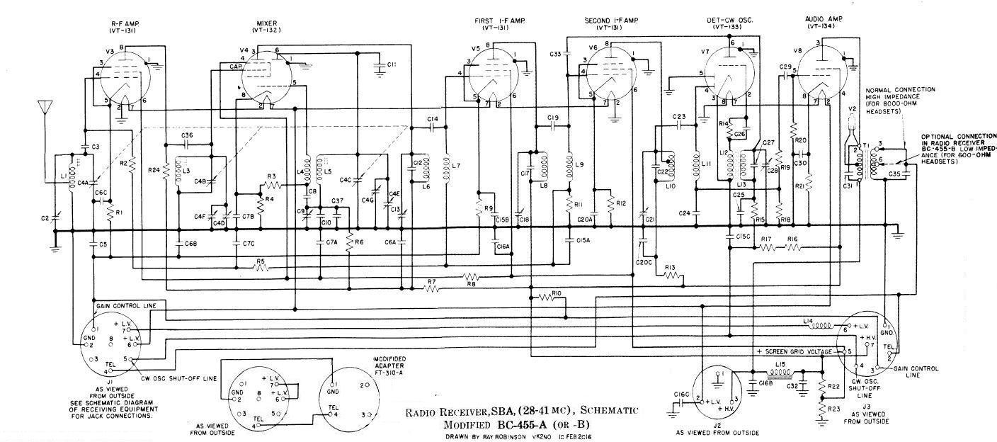
Figure 1: SBA Schematic
The LT choke L14 was missing. I added one. The neon protector on the output transformer was missing, so I added one. The IF cans and BFO were dismantled and examined, but nothing had been changed inside them. They were re-installed. The IF transformers had different dust caps, 2 bakelite and 1 metal. The web photograph also shows a mixture, but on different transformers. I decided to change them all to metal caps.
All the valves, were correct, except one. The first IF should be a VT-131 (12SK7), which is a remote cut-off pentode. There was a VT-131 (12SJ7) plugged in, which is the same, but a sharp-cut-off pentode. Since this receiver has no AGC, just the RF gain control, I decided to leave it as is. The valves were wired in parallel for 12 volts. I rewired them for the original 24 volts.
COILS
The coil box contained three coils, and all were very different to the originals. All three coils inside the coil box had been modified.
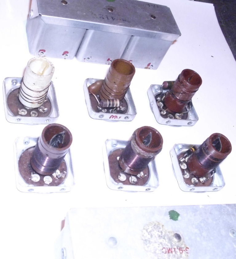
Picture 11: Top Row Coils (28-41 Mhz), Bottom Row Coils (6-9.1 Mhz)
Left to Right, Antenna, RF, Oscillator
It looked like the original 6-9 Mhz coils had been stripped and re-wound. They were originally many turns (approximately 20) and now were all about 4 turns, with turns widely spaced. The antenna coil was 4 turns, and tapped at ½ a turn from the earth end. The RF transformer had the primary completely removed and replaced by a 10 K ohm resistor, and there was a 50 pF coupling capacitor added. The secondary was now just 4 turns widely spaced. The original coils had fixed slug inside them, but now only the oscillator coil had its slug. The oscillator coil was 4 turns, arranged as 2 turns close wound near the bottom, and 1 turn at the top. There was an added 130 pF padder capacitor for the oscillator, across the C9 trimmer and fixed C10.
I noted all the changes, photographed them, and reassembled the coil box. I then redrew the schematic and parts list. The RF coupling capacitor I called C36, and the padder capacitor I called C37. The new plate resistor I called R24. I added these to the schematic and parts list.
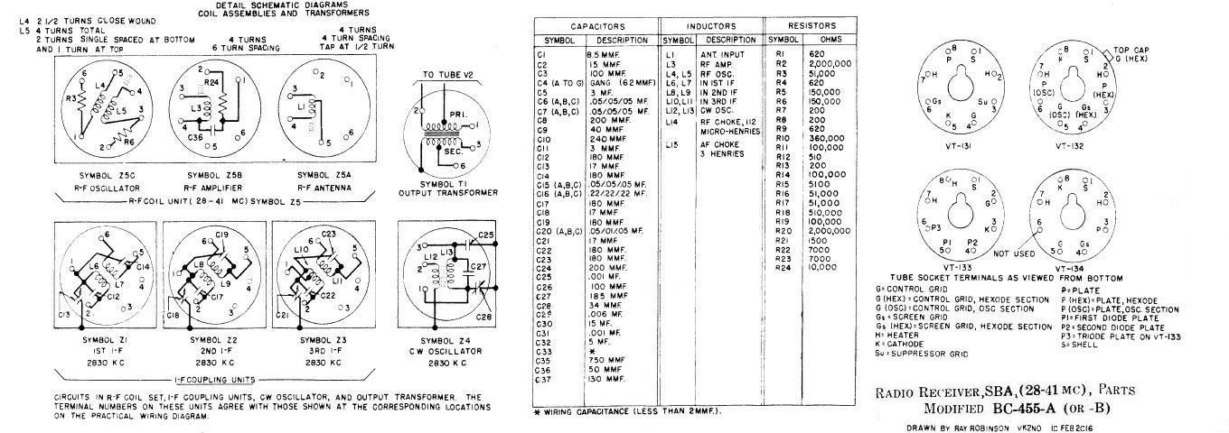
Figure 2: SBA Parts
I used a signal generator to inject 2830 Khz into the top cap of the mixer. All the IF transformers aligned easily on both receivers. I then connected the generator to the antenna connector, and used 30 and 40 Mhz frequencies to tune the RF and oscillator coils. The dial was a little out, so I went backwards and forwards until I got them close to the dial markings. The sensitivity for 30 Mhz was 10 uV for a 10 dB signal to noise, and at 40 Mhz it was 4 uV. The BFO was tuned for a reasonable note. I used 6.2 and 8.9 Mhz for the BC-455 and it also aligned easily. The BC-455 BFO was not working, until I discovered and reconnected the broken wire. It then aligned correctly.
![]()
Picture 12: Testing using the I-84B Test Set
CONCLUSION
This is an un-common receiver and it has had a hard life. It certainly looks it. I was lucky to find it, as there were probably not many made, for the short time that it was needed. The performance is surprisingly good for that era.
REFERENCES
MANUAL, RADIO SET SCR-274N, TO 12R2-3SCR274-2, 15 February 1943
COMMAND SETS, CQ October 1965, p 34-37, Gordon Eliot White
BLIND LANDINGS: LOW-VISIBILTY OPERATIONS IN AMERICAN AVIATION, 1918-1958, by Erick Conway
HISTORY OF RADIO FLIGHT NAVIGATION SYSTEMS, Radar World http://www.radarworld.org/flightnav.pdf
RADIO NAVIGATION AIDS, Roger Meyer http://www.airwaysmuseum.com/Radio%20Navigation%20Aids.htm
ISLE OF MAN ATC IN THE 1940s http://www.island-images.co.uk/ATC/zRon1940s/z1940s.html
Copyright
Ray Robinson