Tube
Radio Australia
 SCR-522 restoration
The Band Changing mechanism Video: https://www.facebook.com/tuberadioaustralia/videos/1840611612843446/
Tube Radio Facebook Page: https://www.facebook.com/tuberadioaustralia
The SCR522 aalso known as T.R
5043 was used in many WWII aircraft and also was in service after the war
in both Military and later in civilian aircraft. These were used by the RAF and
RAAF and US air force.
They were a very widely used Very High Frequency Transmitter / Receiver
operating in the 100 to 150 MHz range. This equipment was recovered from three
locations, One in Bundeena, and the units were heading for scrap, the Dynamotor
was found in a cleanout sale in Guilford NSW, and the other parts from the
Wyong swap and donations from the guys in the Ausmilsig group as well as other radio friends. Special thanks to Dave Prince, Ray Robinson, Morris Odell,
Brian Clarke, for supplying parts needed to complete this job. The unit is very well built and also heavy
for a low power output of, (12 to 18 watts) weighing in at 22 kg and another
16kg for the associated Dynamotor power supply. They are a mechanical
masterpiece given that it selects 4 channels that are preselected by setting
and locking the cams on the receiver and transmitter. Two cams for the RX, and 4 cams for the TX. The solenoid then ratchets the
cams to the position selected from the control box. The link above shows this
in operation and it really scares you the first time it does it…
General
Description
The SCR 522 is the American version of the British TR 1143
transceiver. Although external connections for both units are the same and
major units are interchangeable, the internals are quite different. (This may
answer the question of why there are such weird sockets on this equipment.)
The American
SCR522 has its own British type number as well, just to confuse the issue,
which is TR5043.
The radio
sets were designed for use in U.S. Army aircraft to provide two way radio
telephone communication between aircraft in flight and between aircraft and
ground stations.
Technical
Data
They operate on any one of 4 crystal controlled channels
lying within the frequency range 100-150 mc. Remote control only was available.
Transmitter
channel D was frequently used as a special use channel, which was automatically
selected at regular intervals by the action of Contactor Unit BC 608A, which
caused a signal to be transmitted for 14 seconds in every minute for DF
purposes.
The set
operated from 24 volts D.C. and obtained auxiliary voltages from a Dynamotor
Unit, type PE-94. The transmitter required 11.5a and the receiver, 11.1a at
28v. The dynamotor produced 300v HT, minus 150v grid bias (Tx) and 13v for
heaters, relays, channel change etc.
The
transmitter contained the following tubes: 2 x VT-118 (832), 3 x VT134 (12A6),
1 x VT-I98A (6G6) and 2 x VT-I99 (6SS7).
The
transmitter tuning was adjusted by plugging in a 0-l ma meter from the Test Set.
The positions and operations are as follows:
1. 1st Har Amp. Plate 50ma FSD
2. 2nd Har Amp. Plate l00ma
3. P.A. Plate.
l00ma
4. RF Indicator Diode 1ma.
5. P.A. Grid
2ma
The
transmitter output was 12 to 18 watts.
The sets
were very popular on 2 metres, with transmitters in use up to the 1970's, when
they were replaced with even smaller black boxes of the SSB type.
Unfortunately
the 522 Tx was prone to TVI problems, and had to be heavily shielded to obtain
peace from the neighbours. Many an Australian Amateur started in the hobby with
an SCR522 transmitter and a crystal locked VHF converter, feeding an HF
receiver from the services.
The 522 was
even converted to operate on 6 metres -
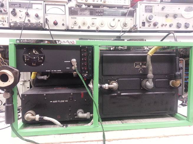
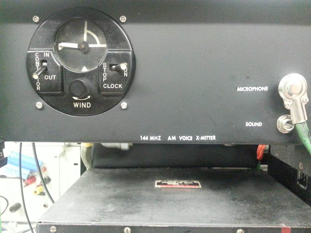
Photo of the Main chassis Reciever and Transmitter with
the TEST control box plugged into the front.

Photo of CHASSIS DURING STRIP DOWN
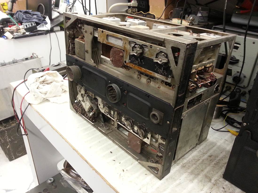
Photo of the two transceivers and the Dyno unit
awaiting service.
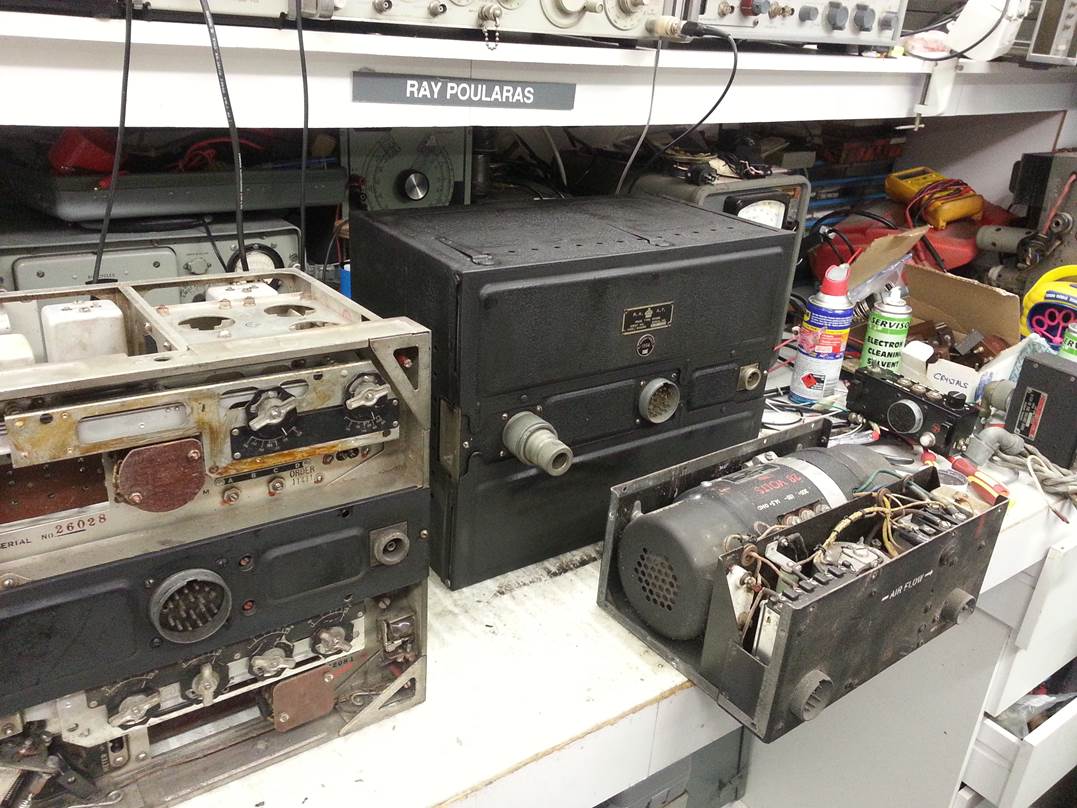
Photo of transceiver one repainted after initial work
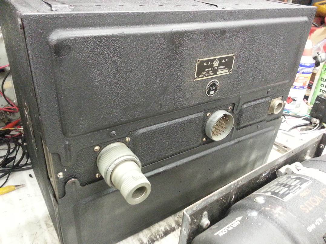
Photo of reciever section type 1 with no noise limiter
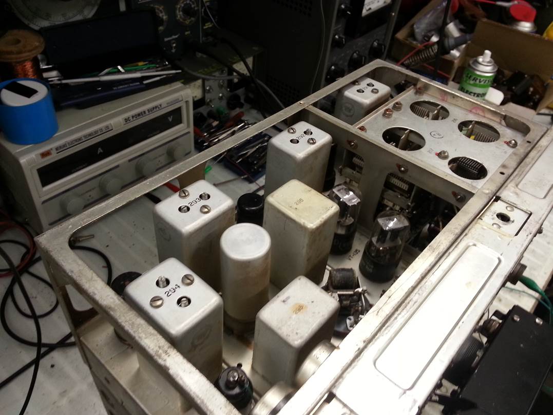
Photo of the Trasnmitter chassis and the modulation
transformer
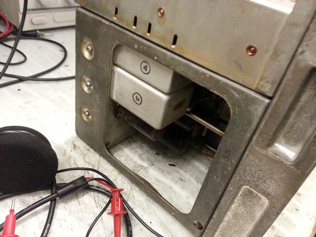
Photo of the reciever type 2. More on this later with
detials of the differences ion the under side of the chassis
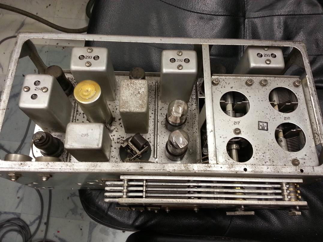
Photo of the type 1 reciever Note the the right there is no additional
tubes on the under side.
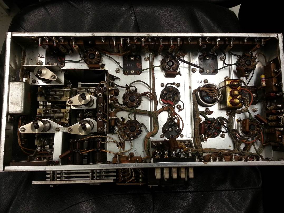
Photo of the type 2 reciever section Note the tube added to the under side,
this was a noise limiter modification.
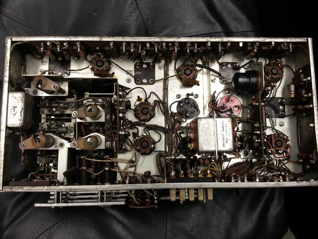
Photo of the type 2 top side very similar from the top.
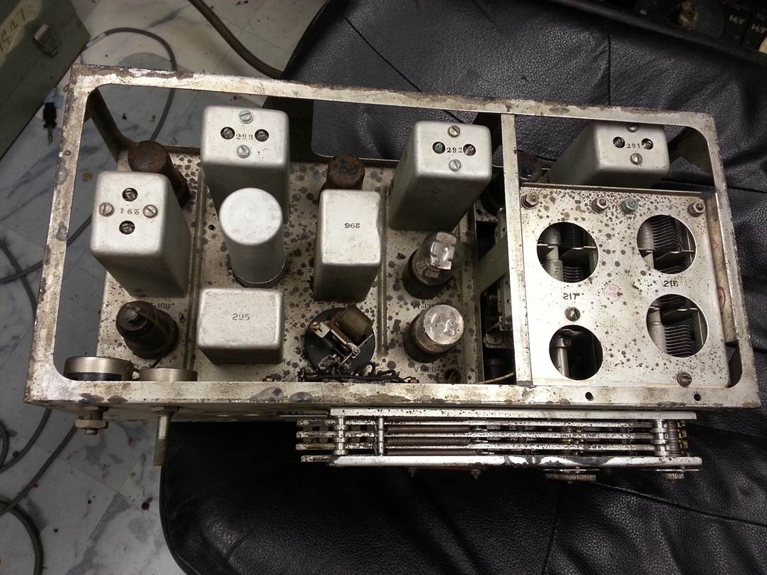
Photo of the junction box and other chassis waiting to
be worked on.
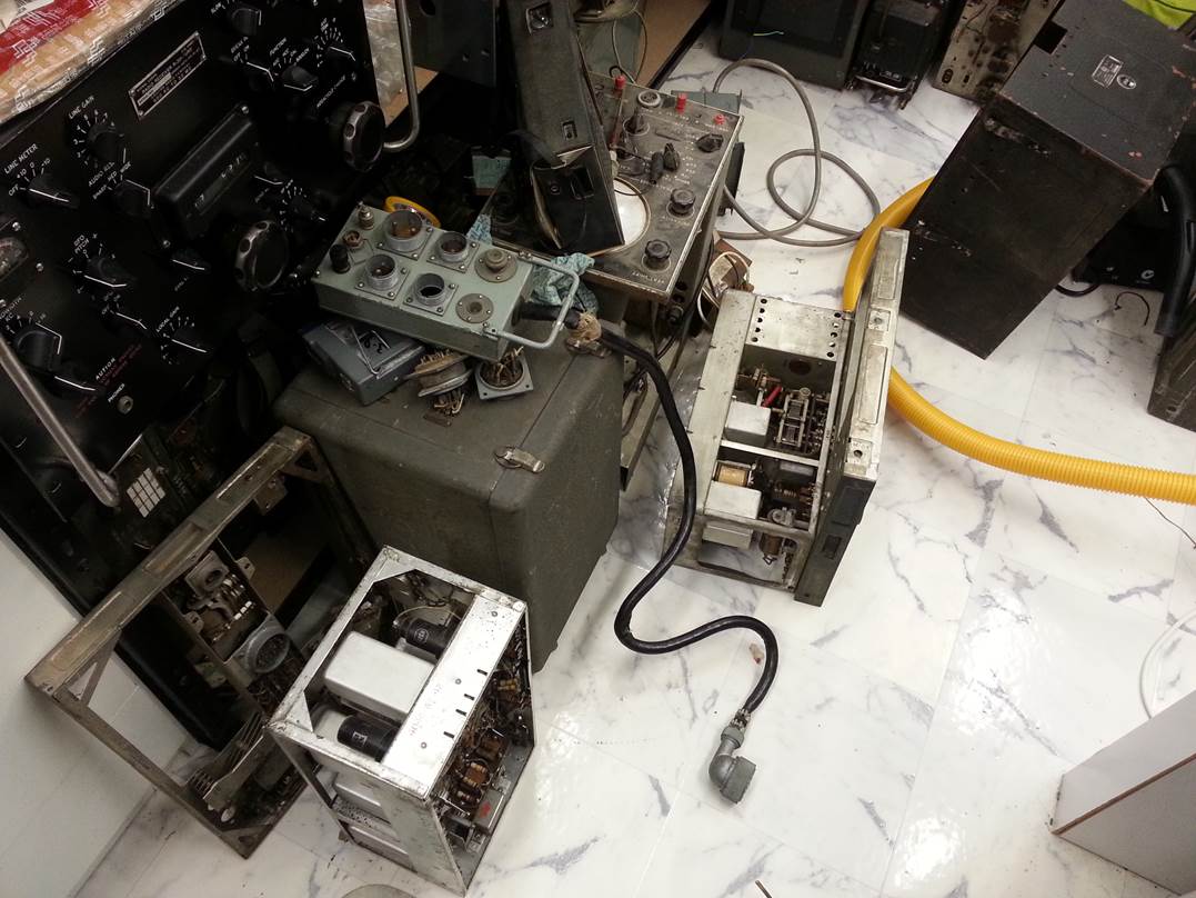
Photo of the Dynamotor 300v -150V and 14.5 volt. This
is the 28V input type there is a 12V typoe as well.
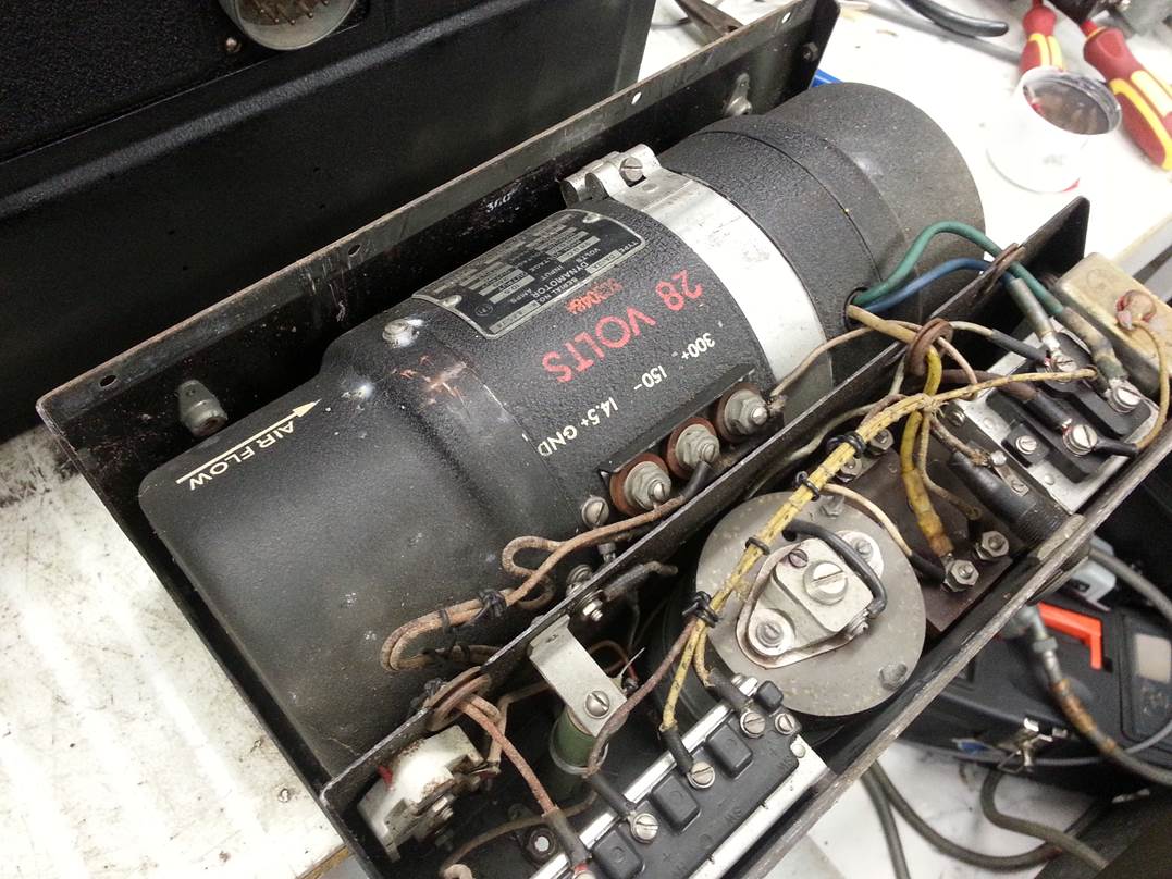
Photo of the transmitted signal on the spectrum
analyser looking at the parasitic
frequencies either side of the fundamental .
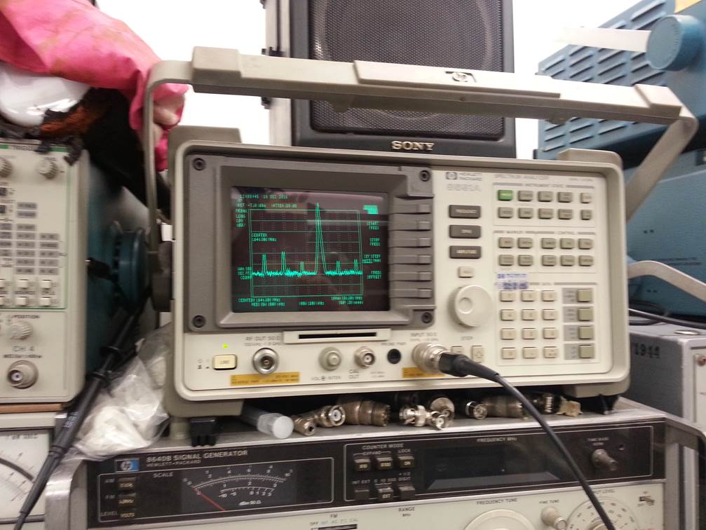
Photo of the test dummy load, this is the correct load
for this from the test set.
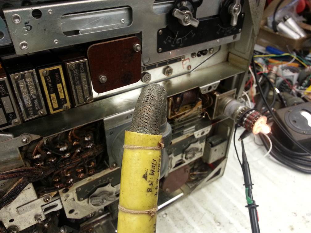
Photo of the display frame being made and painted
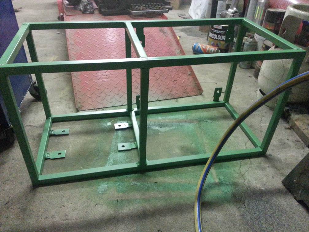
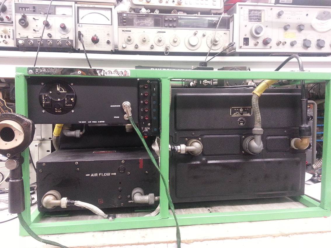
Photo of the unit mounted, with the test meter and
junction box assembled.
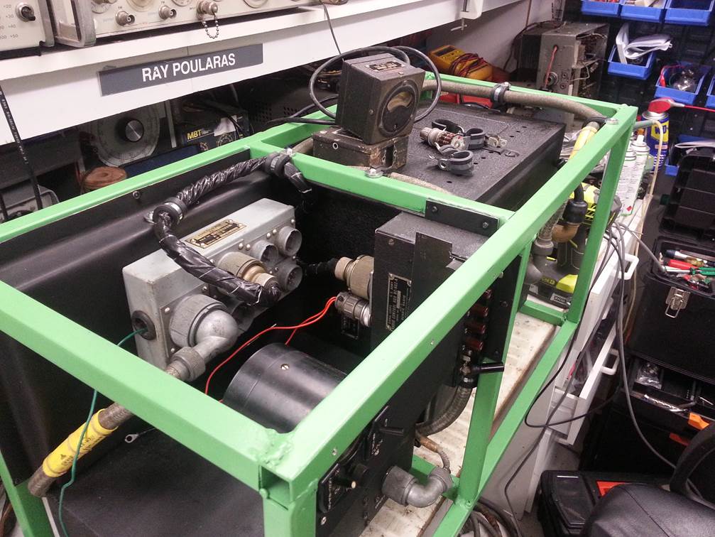
Photo of the Choke in the transmitter that had failed,
this caused the Modulation pre amp tube to be missing
the HV to the plate, although I had RF I had no
modulation, Note the ACME stamp on the replacement from another chassis.
The transmitter always
had RF output and the mike circuit was working as I could hear it in the
headphones, just no Modulation.
So l traced the Mike
into the TX where it goes from a Balanced Mike input through a transformer T158 and relay R131, there was signal…..
Looking at the 6SS7 yes
a SS7 never seen one, there should have been output, so I looked at the input
to the two 12A6’s Nothing on either grid…?
Hmmm, well a quick
check of voltages and there was no HV to the 6SS7, so looking at the Choke 126
I found it Open.
I tacked a little choke
I had across the dead choke and it made no difference. Hmmmm
must need that specific value…
Looking at the spec it
was a 2000 Ohm, 1mv choke, so I when looking at other dead chassis and found
one… Funny thing the transformer brand was ACME… yes the Road Runner ACME.. I always thought
that it was a joke by Warner Bros.. Does
this mean it’s going to fail spectacularly in a cloud of smoke, like it did in
the movies… who knows..
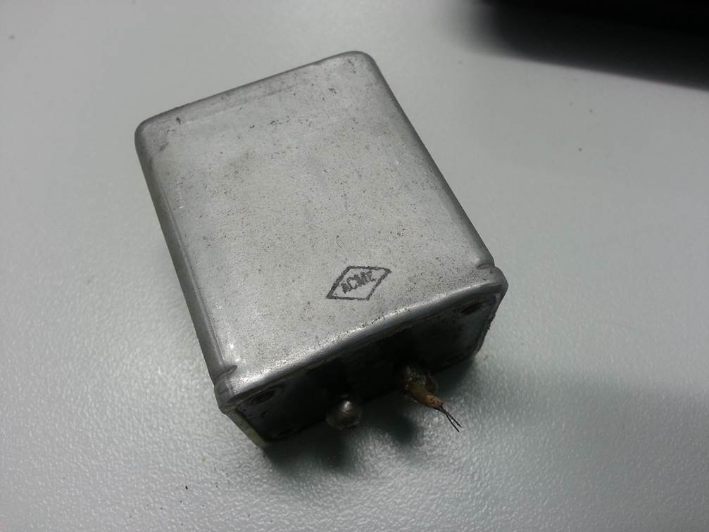
Photo of the under side of the choke.
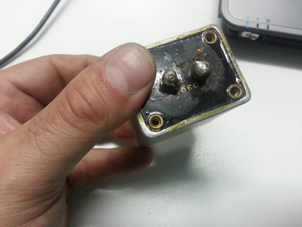
Photo of Modulation Success, the transmitter and reciever
on chassis 1 are now functional.
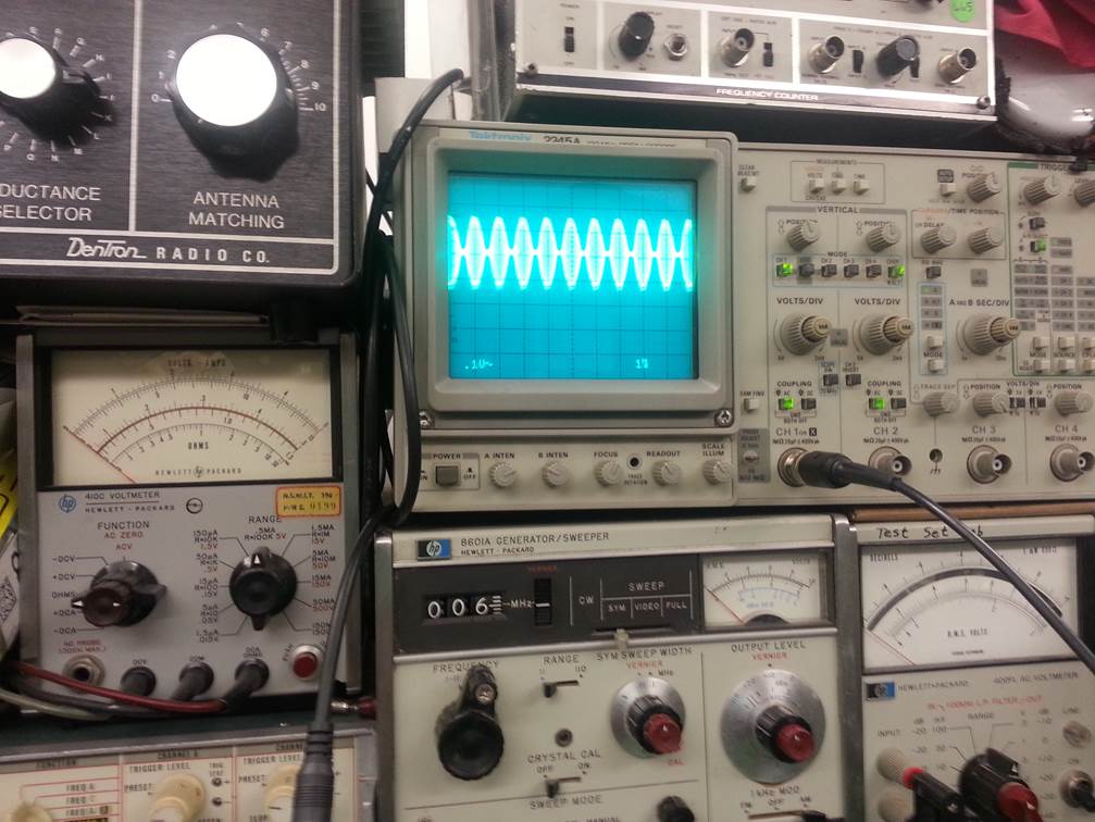
Photo of the under side of the transmitter chassis,
note the ceramic sockets.
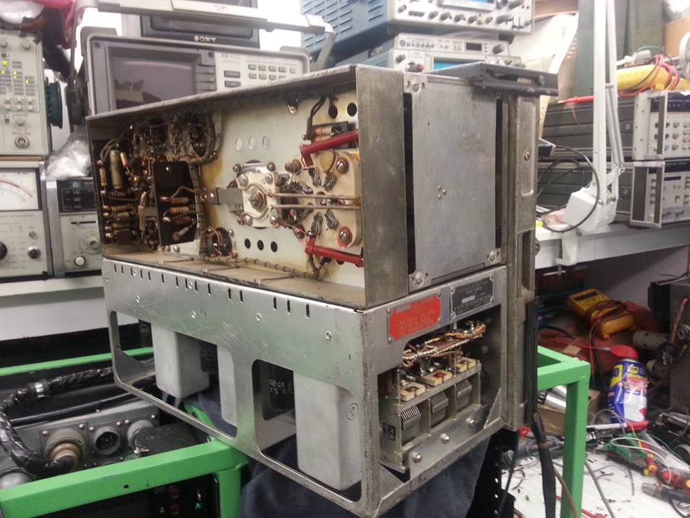
Photo of chassis sitting on top of the display for diagnostics
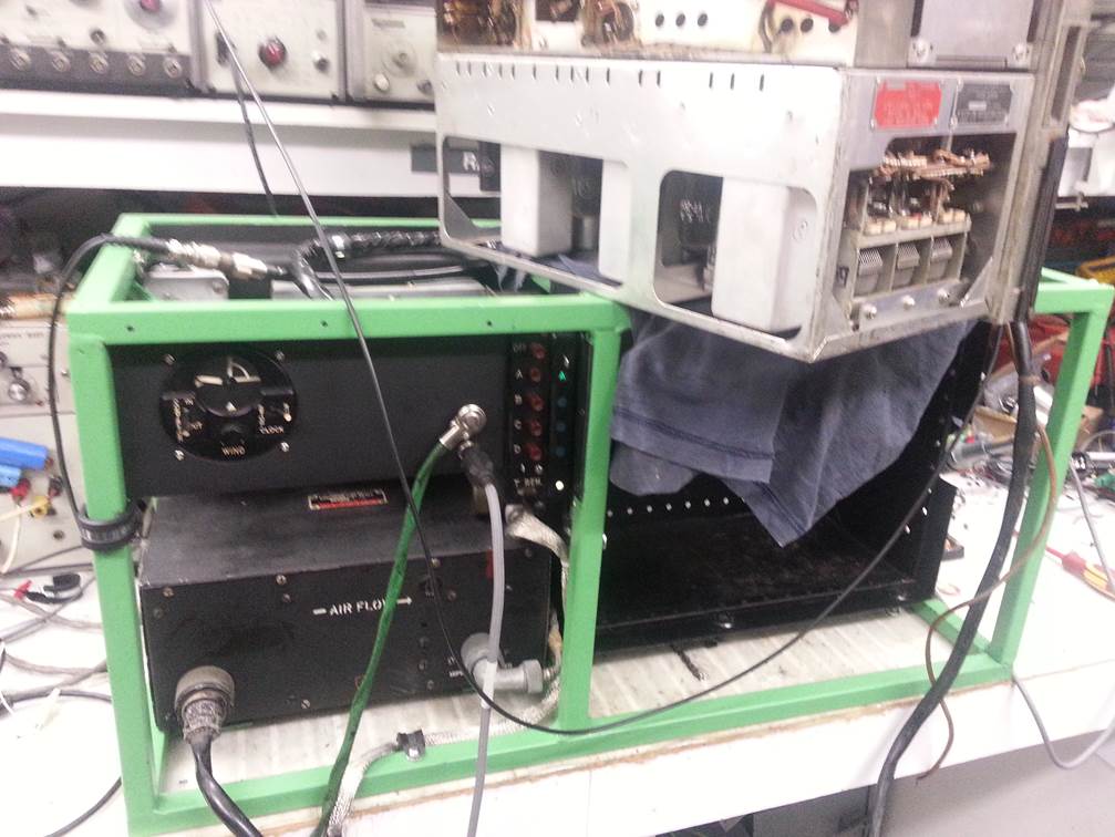
Photo of the completed setup, now for the second one.
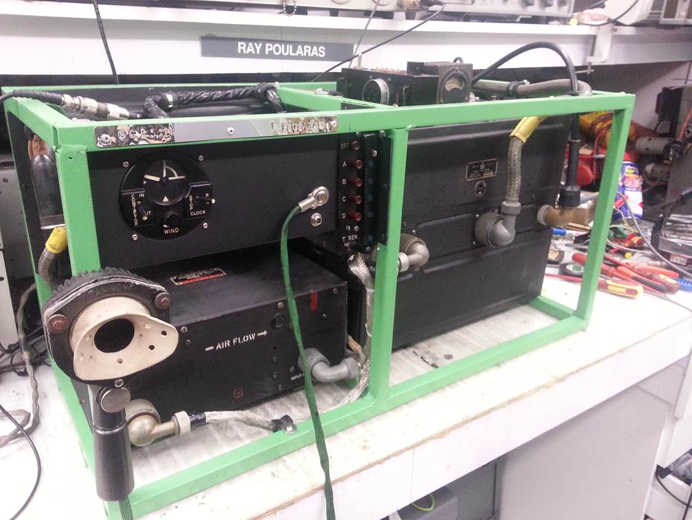
Photo of the Mechanical clock Pipsqueak..
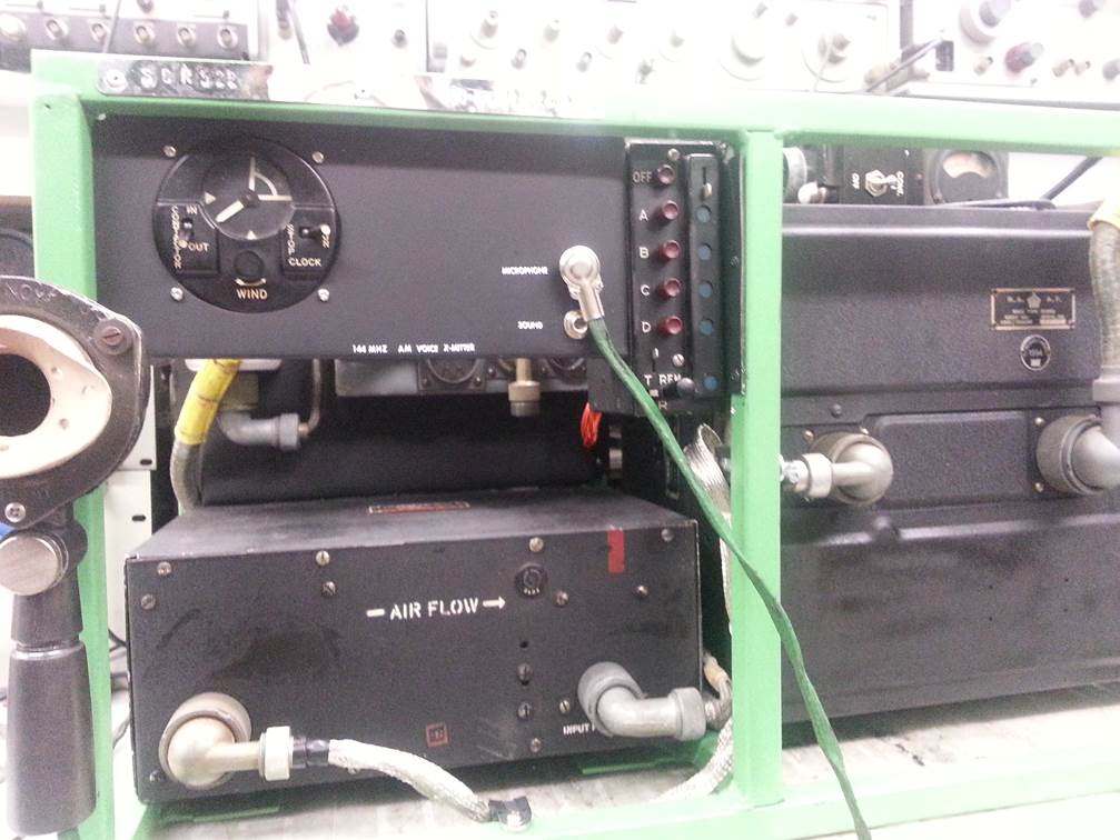
Photo of that clock…
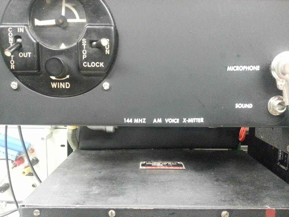
Final installation with the nice hand mike found in a junk pile.
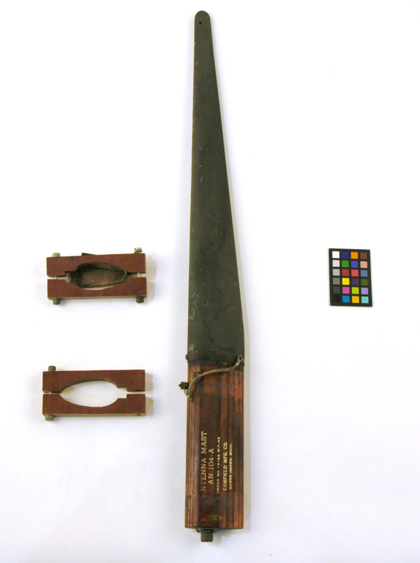
Antenna Mast, Communications Radio, AN-104-A, SCR-522 used on the P51
Mustang.
SCR522 Documents. All you need to make it run…
Airborne_radio_equipment_handbook_1943.pdf
SCR-522_Instruction_Book_Temporary.pdf