Tube Radio Australia

SX-28A Restoration Project


Some years ago I came across a SX-28A, and with the intention of restoring it brought it home. To my surprise it sort of worked so it took a number in the restoration projects pile. I finally decided to do some work on it and started with the Audio section as the audio was very poor. I found that some modifications had been done to the preamp, with (A Miniature tube installed) and some additional components were missing. The output transformer was not original one for the set and the power supply had been modified with non original rectifier. Also the choke was MIA...!. I managed to get hold of the right parts and reverted the modifications including a rebuild of the push pull output stage. The radio sounded much better and at this time I left it at that stage so I could use and enjoy the radio.
Now some three years later while listening to HAM chatter on 80M I finally could not stand the degrading performance and the absence of the top band so out it 
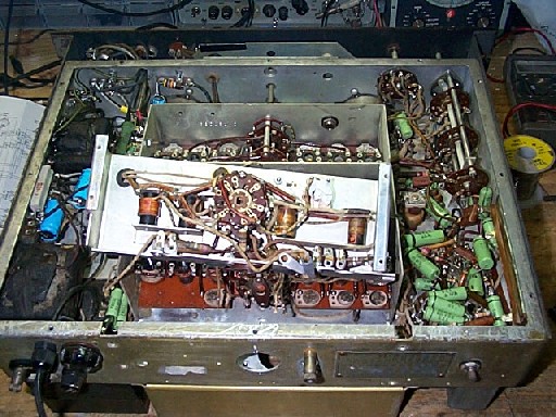
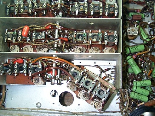
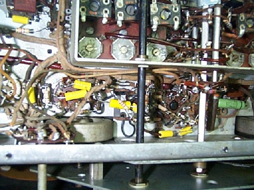
came and down to the lab for some repairs. Well I started with the RF deck and bellow you will find some Pictures of the RF deck restoration. Included are some interesting problems I found along the way.


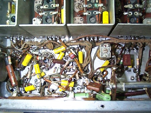
AF Section after renewal.


The latest work
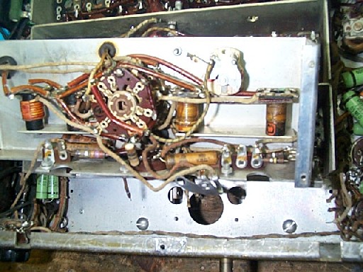
Well since I had already been in the output stage I started at the front end.
After finding a good diagram the surgery began.
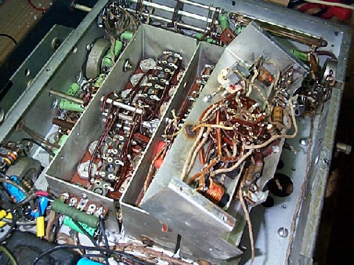
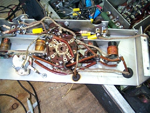
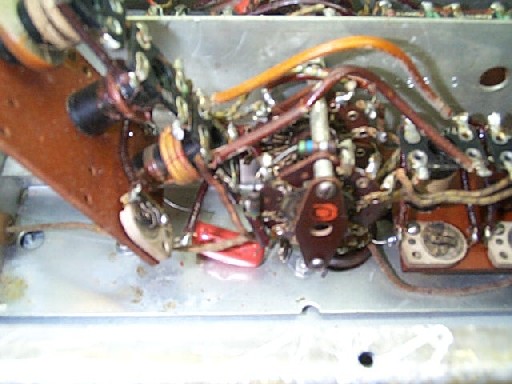
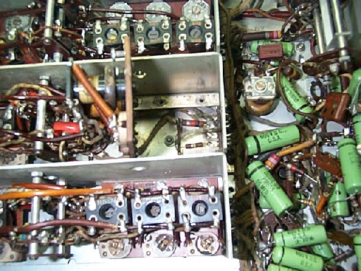
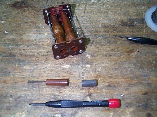
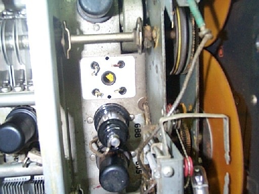
I Started by disassembling the first RF stage. 
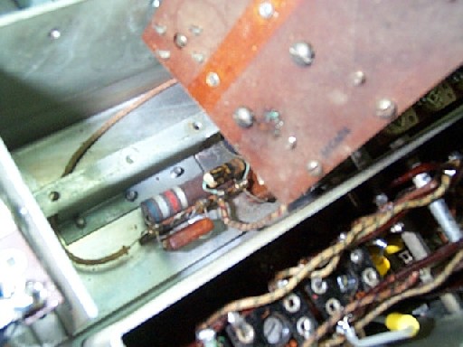
Bellow is the process with some pictures of the stage dismantled and being restored.


1st RF Stage Removal Process.


1 - Firstly obtain a thin Silver or Black Permanent marker pen. This will assist in marking wires so that you don't get mixed up as they are hard to track through the harness.
2 - Mark the wires to the first RF stage, (This is the stage to the rear of the set).
3 - Remove the two screws from the rear band change selector plate and undo the coupling in the centre of the unit.
3 - You will have to remove the wires between the 1St Stage and the chassis to get it out. (be sure to mark the wires).
3 - Remove the first stage and replace everything. (NB On my set one capacitor was missing from factory on the 1St and Second Stage. You need these.
3 - Put the stage aside for later reassembly.


This is the 1St RF stage ready to work on. (Note the components under the Coil Plates). It is Imposable to get to them without removal of the stage.


The 1St Stage Poped up and from the Left Side.


The 1St Stage after the renewal process.


2nd RF Stage Restoration Process.


The 2nd Stage during the renewal process.
Note.! To work on the following stages this method saves time and with care not to break the band switches can be performed without the removal of the subsequent stages.
Remove the three screws securing the coil block and Very Carefully move it aside to access the components bellow. Replace all Components.


The 2nd Stage left side during the renewal process.

Mixer Stage Restoration Process.


The Mixer Stage during the renewal process.

To renew the components remove the three screws securing the coil blocks and lift carefully as shown. replace all components under the coils.

Oscillator Stage Restoration Process.


The Oscillator Stage during the renewal process. (Note the fried resistor). Replace Everything Here...!.


The Oscillator Stage during the renewal process. Note ! (The first stages have been replaced into there positions to assist with troubleshooting the Oscillator Stage).

AVC and S-Meter Stage Restoration Process.


One of the interesting problems with this radio is that intermittently it would perform well and other times it was deaf as a post.
I found that one of the slugs in T6 the AVC section was broken so surgery was needed and some epoxy to repair the damage.

Note the two colours of the slug. This had been broken for some time and who knows maybe from day one.


The AVC Stage Top View if the Transformer removed. During renewal.


The AVC S-Meter Stages after renewal.

The Noise Limiter Stage Restoration Process.


This part was easy just replacing all of the out of spec components. All of them.

The IF Section Restoration Process.


This is a critical part of the process. Note that in the IF cans there are resistors and Capacitors that will need to be replaced.
It made a big difference to the performance of the receiver and the operation of the selectivity Crystal Fillter Section.


The IF deck after component replacment.


SX-28A Diagrams.

 SX-28A-PDF1

 SX-28A-PDF2

 SX-28A-PDF3

The Results.

The results after allignment are quite interesting. I have seen many modifications for the SX-28A and 28 but after carfull selection of components and allignment

the receiver is so sencitive on all bands that the RF gain must be set about 50% as it is too sencitive otherwise.

Once you find a faint station is is very nice to turn up the RF gain and bring it in. Sencitivity is good all the way up to 40MHz.

More to come on the alligment proceedure and some photos of the finished product later.


 Home