MACKAY 1937 EXPEDITION RADIO
by Ray Robinson
INTRODUCTION
I was contacted by phone in July 2004 by John MacIllwaine, President
of the Historical Radio Society of Australia (NSW branch), and asked if
I would restore a radio for Dick Smith. The radio was used on the
Mackay expeditions. I had never heard of Mackay, but I had heard of Dick
Smith, so I said yes. Apparently it was donated to Dick Smith by the Mackay
family, and it will be displayed in the Dick Smith museum. I eventually
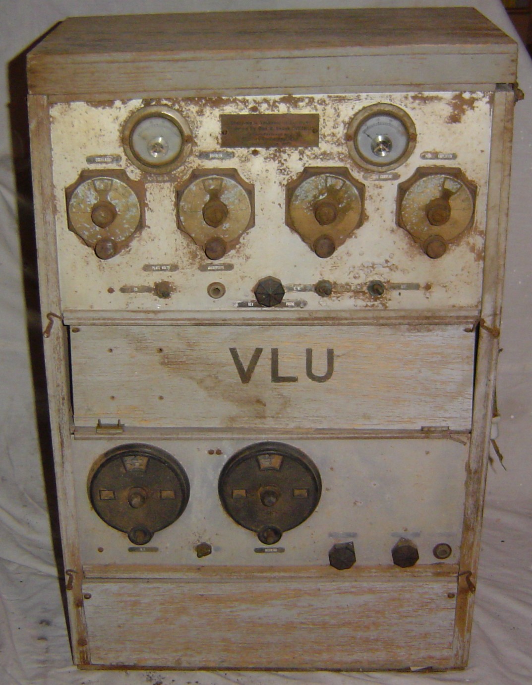
received the radio in 2005. I was surprised at what I saw. It was a home
made radio, with a transmitter and receiver in a plywood box. It looked horrible,
and I wondered if I had made the correct decision. It was so bad, that it
required "restoration" rather than "preservation" to prevent further deterioration.
RADIO CONDITION
The plywood case was in poor condition and coming apart,
the wooden layers separating, and peeling back in ripples. It had
little external paint left, the top was broken off, and the two opening
panels half falling off their hinges. The exterior was very dirty, but
the inside was worse as it contained a lot of red dust, some dirt, and
a fair amount of dried grass. At least it had not been stored in wet conditions.
I removed the top lid, and examined the transmitter. The front panel
was awful, corroded, dials seized, and the lettering missing. The transmitter
was missing its valves, but looked complete. Upon extraction, it was
surprisingly clean underneath. The intermediate plywood shelf came out,
and revealed the receiver. It was in lovely condition, no dirt, it
had its valves, and they looked almost new. It appeared complete, and
the underside was clean. The front panel was dirty, with some labels missing,
the dials seized, and the bakelite verniers looked fragile. There were
no headphones, no power supply or batteries, no microphone, no morse key,
no transport box or case, and of course no circuits or documentation. I
sat and thought about it for a while. This was not going to be simple
and would take a fair amount of time. So I drew up a plan, restore the case
first, then the receiver, then the transmitter, and then build a power
supply. Not to be rushed, I took many photos of the outside and inside,
and drew diagrams of the wiring.
HISTORY
I began some research to find out who Mackay was, and what the radio
was used for. There was a dirty brass nameplate on the front, which read...
Short-wave Transmitter-Receiver
Designed by Don B. Knock VK2NO
Manufactured by Sterling Radio Pty. Ltd.
June 1937
So I had a starting point, the date, the designer, and the manufacturer.
Some documentation that was eventually supplied with the radio, was
provided by Dick Smith's PA (Marilyn). The typed description mentions UX199
valves, a filament control, and broadcast band radio stations, so I concluded
that this description was not for this radio set. There was a copy
of an article titled Radio on the Mackay Expedition, by
Don B. Knock, Australian Radio News, May 26, 1933, which contained a
photograph showing a transmitter, probably an airborne transmitter, as it
had 201A valves in it. The set I am restoring is a ground transmitter and
receiver. One point of interest was that the photo showed a group standing
in front of an aircraft and the caption mentions H. K. Love of the RAAF.
Love went on to form the Kingsley Radio Company which made the famous AR7
receiver in WW2 (a copy of the HRO receiver). There was another photograph
supplied, from the Sydney Morning Herald, February 1937, but it was not good
enough to show the radio. It did show a bush camp with what appeared to be
a "coffin" style receiver with a side knob, balanced on top of a pile
of stores.
Inside the radio was pinned a small piece of paper with some frequencies
scribbled on it. When I turned it over, it was a business card, which said....
Don B. Knock
14 Yanko Avenue,
Waverley NSW
phone FW 2443
Experimental Radio VK2NO
Portable Radio VK2NU
Radio Editor "The Bulletin"
252 George St.
Sydney NSW
Phone B 7971
His callsign has been reissued, so there was no help there.
The Alphabetical phone numbers, and the need to have 2 call signs will
help verify the period. I contacted the Bulletin magazine to see if they
could provide more information, but they could not help. I found a series
of articles about the life of Don Knock, thanks to several friends. An internet
search found the journals of the 1930 Mackay expedition, but this radio
was labeled 1937. I found a web site for the Power House Museum that has
Donald Mackay's bicycle, used to ride around Australia in 1901. I also found
an article titled Radio Tests in Central Australia, by H. K. Love, Listener
In, 26 July 1930. Another web site has the generator used in the aircraft
on one of the expeditions. I finally found a book by Frank Clune which was
a biography of Donald Mackay. This provided the dates and details of his
4 expeditions to map Central Australia by aeroplane, this radio being used
on the last expedition in 1937.
CASE
The plywood case was an upright design, with the receiver at the bottom,
with an enclosed shelf under it. The shelf had a hinged closing door,
affixed by brass hinges and held closed by small hooks and eye screws.
It was probably intended to store headphones, notes and pencils. Inside
it were 4 terminals and a fuse, that connect the receiver LT and HT wires
to a 4 pin socket mounted on the left hand side of the case. A battery
cable would probably plug into the socket. One terminal had a dial light
globe attached as the HT fuse. The terminals were not covered, so you could
come in contact with them, when stowing or removing the headphones. They
were live when the batteries were connected, even if the receiver was switched
off. The receiver slid down from the top, with the front panel edges engaging
with vertical slots. A better design, would have been achieved with the receiver
sliding out the front, with 2 screws at the rear to hold it in place. As
it was, the transmitter has to be removed, before the receiver can be accessed.
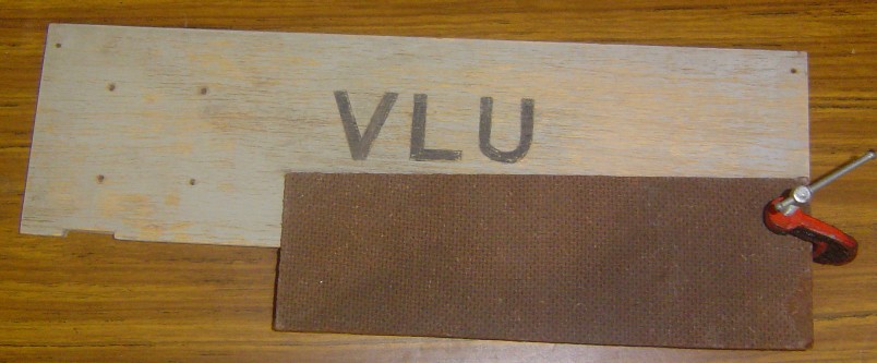
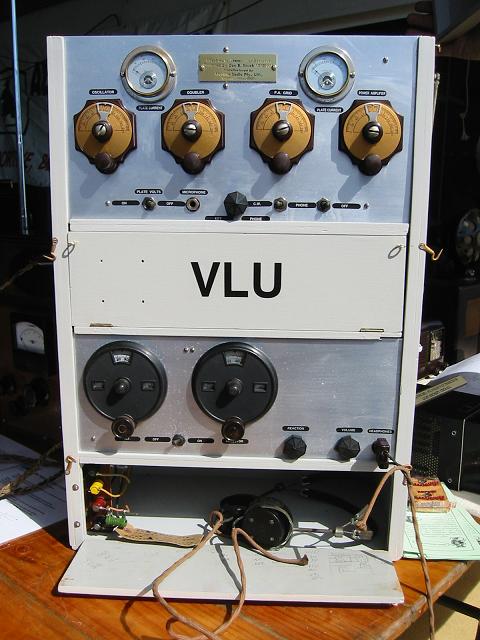
Above the receiver, was another enclosed shelf, with a similar opening
door. The door had the call sign VLU painted on the outside, and pencil
notes written on the back. It was probably intended to store a morse key
and a microphone. There were 4 empty screw holes in the door, which may
have been used to mount the morse key. The LT and HT wires from the transmitter,
are attached to two sockets, each having 2 pins. The socket rear terminals
were not covered, so you could come in contact with them, when accessing
the key or microphone. These were also live when the batteries are connected,
even if the transmitter was switched off. The transmitter also slips in vertically,
using slots engaging the front panel. A wire brace across the front pulls
the sides together. The top cover was hinged, to allow access to the crystal
socket for changing the transmitter frequency. When closed, the top cover
has a notch to clear the aerial wires. On the right hand side of the case
was a dual position, dual, contact ceramic knife switch, for manual change
over of the aerial from the transmitter to the receiver.
I removed the transmitter and placed it in a cardboard box and put
that aside. I also removed the receiver and placed that in another cardboard
box and put that next to the transmitter. I removed all the screws,
hinges and sockets, and placed them all in a third cardboard box. The
door from the middle shelf, has the callsign on the front and pencil notes
and frequencies on the back. I got some tracing paper, and traced the VLU
legend, so that I can repaint it later. I used a spray can of clear lacquer to
protect the hand written notes on the rear of the panel.
I sanded all the rough wood. It had particularly bad warping
on the bottom. The wood where all the hinges were attached was cracked, split
and broken. I used clamps and glue to hold the broken and warped wooden parts
together. I painted all the wood with pink primer to prepare and preserved
the wood. I then painted the final two coats with grey oil based paint,
which matched the original colour. The original hardware, the hinges,
hooks and eyes, were all rusty and needed replacing.
They looked as though they were originally made from brass plated steel.
I managed to find some new brass hinges and screws, and some new eyes for
the latches, but no hooks. I finally had to spray the original hooks
with gold paint, to reuse them. I screwed on the hinges, attached the front
opening panels and the hinged top, then added the latches. I made up
a new VLU legend on a computer, scaled it to size using the tracing paper,
printed it on Decal water slide transfer paper, and applied it. I then spayed
it with clear lacquer to protect it. The wooden case was now complete.
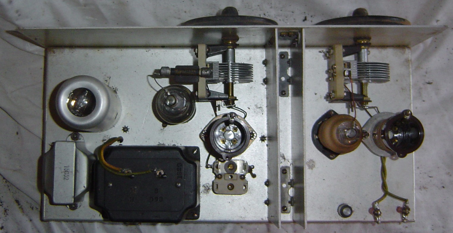
RECEIVER
I started work on receiver. It was in good condition, the underside
was very clean. The top side was good, no doubt due to being housed within
the cabinet undisturbed, and covered. This meant that it was difficult
for dirt to get in, but even so, there was some grass inside. The components
were clean, and the cotton covered wires were in good condition. The front
panel was corroded, the dials had red dirt in them, they were seized,
and missing the knobs. The front panel was also missing half the labels.
I removed the dials for cleaning. One tuning capacitor was loose.
I adjusted the friction, being careful to avoid a short circuit. I tightened
several screws as all the coils were loose. The coil wire windings were
cotton covered wire, but not lacquered. I considered fixing/sealing
them with lacquer, but decided not to. This was a restoration, so any
attempt to improve the radio was to be avoided. I traced out the circuit,
and it appeared to be a regenerative detector (valve type 15), with
one AF amplifier (valve type 1D4), and one RF amplifier (valve type KF3).
I checked the resistors and they were all within tolerance. I looked
up the valve characteristics and they had 2 volt filaments. I applied
2 volts DC, and switched ON, the filaments drew current, which was a
good sign, as it meant no one had burnt them out. The AF amplifier used
a speaker transformer as a choke, and had a phone jack, with a capacitor
from the AF amplifier plate, which means it required high impedance
headphones. I located a pair of suitable period headphones. I applied
DC to the HT and negative wires (it uses back bias), and slowly wound
it up to 90 volts. I heard some noise when adjusting the tuning capacitors
(they needed some lubrication). The set oscillated when I turned the
reaction control up, which was a good sign, it meant that at least
two valves were working. I connected an aerial, but not much happened. I
advanced the HT to 125 volts, and heard a station. The controls were
touchy without the vernier drives attached, and the set was also microphonic,
which is common with filament valves. I used a signal generator to determine
the frequency coverage, which was 4.75 to 13.7 mhz. I lubricated the capacitors
and potentiometers. It was amazing that the receiver worked, with its original
paper capacitors and resistors.
I cleaned the vernier dials and they came up nicely. There
was some wear on the bakelite around the knob shaft so they were a little
sloppy. I was donated 2 knobs by a friend which were close to what should
be there. The centre bakelite cover for the main shaft had gone brittle
with age. I removed the front panel and polished it on a buffing wheel,
but could not remove the deep pitting and corrosion. Another approach
was necessary. I cleaned the front panel with warm detergent, then etched
it with sodium hydroxide (Draino drain cleaner). I then anodized the
front panel in sulfuric acid (battery acid) at about 2 amps. The panel came
up nicely, but the pitting was emphasised greatly. So that was no good. I
then sanded it with steel wool in one direction only, to remove the anodizing,
and then sprayed clear lacquer on it. That was the best I could do,
as I did not want to replace the front panel. It had a long score mark
(probably for marking up during manufacture) and a couple of elongated holes.
This probably means that this was a "one off" model and possibly made
to a time schedule. It will look as though it has been out in the outback.
I reassembled the receiver and put in a cardboard box for protection.
TRANSMITTER
I started work on the transmitter and cleaned the dirt from
the chassis. I removed the front panel, and cleaned the dirt off with detergent.
I scrubbed it with wire wool and lacquered it. I did the same with the
brass nameplate, and then cleaned and wire wooled the brass meter bezels.
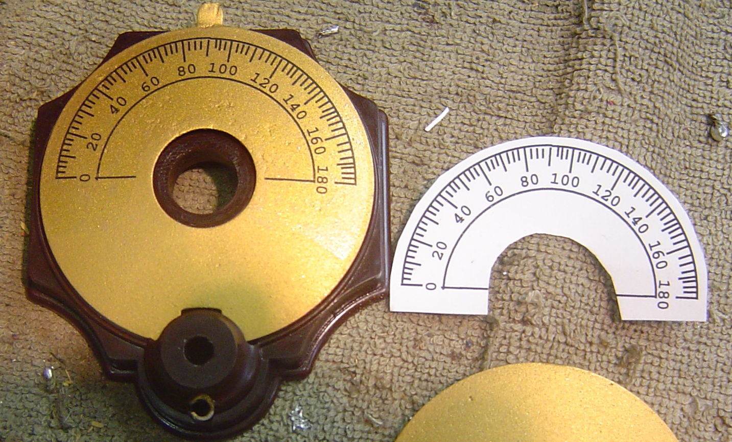
The four ORMOND dials were corroded and seized. I disassembled them
(each dial had 11 parts), and cleaned and lightly oiled the bushes
and bearings and knobs.
The dial graduations were silk screen black lines and numbers
(0-180) on a gold painted scale. The scale was corroded and the markings
hardly legible. I sanded the dials scales smooth, and painted them
with gold paint. I made a new dial scale on the computer, and laser printed
it on to "Waterslide Decal" paper (about $1.30 a sheet). I cut
these out with scissors, soaked them in water, and applied them. I made
them semicircular, not an annulus, as the scale is convex, and the
decal needs to bend a little. I then applied a thin coat of lacquer to protect
it, not too thickly, as it will attempt to dissolve the decal. Two thin
coats were required.
I reassembled the dials, then mounted them on the front panel.
The rusty screws were cleaned, and the heads lacquered. Any spare holes
were filled with a screw. The front panel had small labels, which were
affixed near each control. Some were missing. They appeared to be a metalised
label with a photographic or inked legend. They looked like Scotchcal
labels but that 3M product was not available then and is no longer available
now. There is a new product called "Adressotak", which is a metalised
adhesive backed label, available in silver or gold, and comes in A4 sheet
size (about $3.75 per sheet). I prepared the artwork on a computer and printed
it on a laser printer then cut it out with scissors, peeled off the backing,
and the self adhesive label just glued on. I copied the original legends,
and made guesses as to what the missing ones might have been. It was
a good result, closely matching the originals.
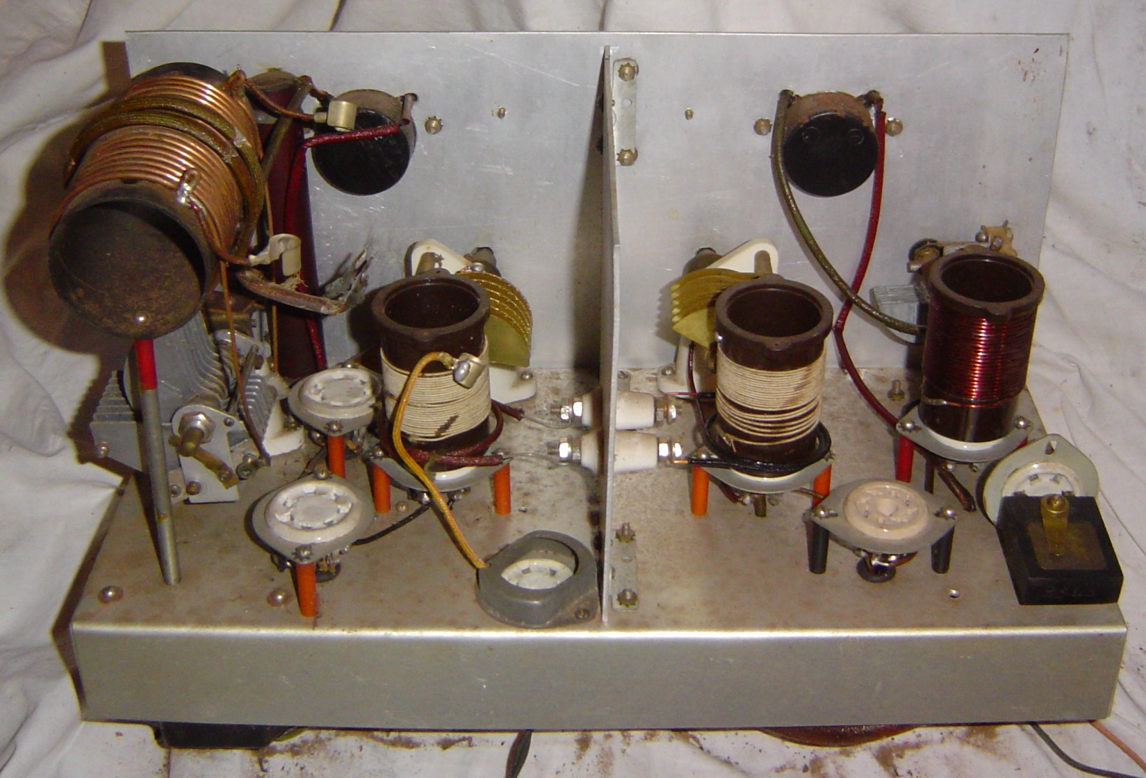
I traced out the transmitter circuit. It appeared to be a pentode
crystal oscillator, with a plate current meter for tuning. The
power amplifier was two valves in push-pull. There was a single valve as
the modulator. The physical construction was generally good, some parts were
well made and constructed. The oscillator section was shielded and nicely
laid out and spaced. The coils plug in on 4 pin bases, one for the oscillator
cathode, and one for the oscillator plate. The oscillator cathode coil
was enamel wire covered in lacquer. The plate coil was made of cotton
covered wire, but the original enameled wire leads to the base were still
visible, which means that it was originally enameled wire, and this
had been cut off and it had been rewound. The grid coil for the power
amplifier has had the same treatment. The coupling from the oscillator plate
coil was a 2 turn link winding, which feeds through the shield to the
power amplifier section. The grid coil had an identical link. The links
were nicely made and laced. There were several extra holes in chassis which
were not used. Many holes had not been de-burred after drilling. There
were also some construction scratches. The tank coil was mounted on tall
posts, and was wobbly and flimsy. The oscillator and power amplifier sockets
were on short posts, mounted above the chassis so they would have good shielding
from the circuitry below. The modulator valve was mounted in a hole
in the chassis. The power amplifier valves were too close to the tank coil,
were actually resting against it. The tall chassis mounted electrolytic
capacitor, the older wet type, was also too close. It had dried out and
the label had fallen off, so I glued it back on. The tank tuning capacitor,
was a different type to the other three tuning capacitors. It looked
second hand and had some bent plates, so perhaps it had been changed.
The tank coil connections to the capacitor were loose, and one had no nut.
The shaft wiper and the shaft coupling both looked home made. One of the
coil mounting tags was sticking out, as though it was added later or
was the wrong size. The capacitor shaft was too close and rubbed on the tall
electrolytic capacitor. The HT bypass capacitor is a long tube with wax sealed
ends, held to the front panel by clamps. It looked home made. I measured
it and it was only 25 pF, very strange. I turned the chassis over, to see
where the lower pigtail passed through the chassis. It went through a rough
un-burred hole, but was floating, that is, not connected to anything!
It should have been earthed. This appears to have been a construction
error. Perhaps it was touching the hole when it was first made. Maybe
it was intermittent, which may explain the modified appearance of the
tank components. When I connected it to earth, the capacitor value read
as 0.25 uF, which was much better. However, it did not change the resonant
frequency of the tank coil, which was 5.2 to 11.1 mHz. The oscillator cathode
coil frequency was 3.4 to 9.8 mHz, which was indicated on my Grid Dip
Oscillator (GDO). The oscillator plate coil did not dip at all. There was
a place on the coil where two wires were twisted together, so I soldered
them, and it then dipped at 6.0 to 10.0 mHz. The power amplifier grid
coil was 5.0 to 8 mHz.
The transmitter had no valves, so I had to identify the types.
The Power amplifier used a 7 pin UX base, with a plate top cap. The 807
valve has 5 pins, so it was not that type. The 1625 has 7 pins, but
was made after 1937. That left the 802 valve, which matched the application
and physical dimensions. This meant that the other valves had to be 6.3
volt filament types. The oscillator valve was octal based, and the
pin connections matched the 6V6, 6F6, and 6L6. The 6V6 was lower power
and was available in 1937. The modulator valve had a 6 pin UX base, a
6.3 volt filament, had a grid top cap, and had to be an audio power
valve. The only candidate was the 89. I had none so I ordered one from
Melbourne. I had the other three valves in my junk box.
The modulator valve was cramped into one corner. The microphone
transformer and modulation transformer were mounted under the chassis,
but poked down too far, such that the wooden partition below the transmitter
had two square rough cut-outs for them. It all looked like an after-thought.
Perhaps it was added later. I placed a 10 uF 600v electrolytic capacitor
across the defunct large tubular vertical electrolytic capacitor, and
hid it under the chassis. I removed the modulator cathode bypass capacitor,
and put a new 25 uF 50 volt electrolytic capacitor hidden inside the
old cardboard case.
It was time to test the transmitter. I found an
early morse key for the transmitter. There was no crystal in the holder. It
was a bakelite holder, with two brass plates held down with a spring clamp.
The slab of quartz was missing so I added an FT243 crystal with alligator
clips. I connected a 12 volt 25 watt light globe to the aerial terminals.
I powered up the valve heaters with 6.3 volts AC, and they all seemed
to glow appropriately. I then applied 100 volts DC, and the plate
current meters showed a little deflection. There appeared to be no short
circuits. I slowly increased the voltage in 50 volt steps to 300 volts.
I monitored the plate current and dipped the meters with the four
tuning controls. The meters are very lively and would benefit from some
damping. They wobble all over the place so finding the dip is difficult
and time consuming. The light globe was glowing. It all appeared to
be working, and the morse key keyed the transmitter properly. Wonderful!
Then the PA plate current began to rise, for no apparent reason, so I switched
everything off.
POWER SUPPLY
The radio uses an external power supply, connected by cables
to sockets on the case. The receiver has a 5 pin UX type female
socket. I found two suitable plugs from my junk box and plaited a cable
from some old style cotton covered wire, and then attached the 5 pins plugs
to each end. The transmitter uses two 2 pin male sockets on the case,
of a type that I have not seen before. I examined my junk box
and found two plugs that were a close fit, but with a wrong pin spacing.
I removed the pins and elongated the holes, such that the pins matched,
and then glued them in place. One has a key, so that it can only be
inserted the correct way, and it also can not be confused with the
other. I plaited a cable from cotton covered wire, to connect these two
plugs to a 4 pin UX plug. The keyed plug is the 500 volts DC and the
unkeyed plug is the 6.3 volts AC.
There was no power supply provided with the radio, and there
was no indication what it might be. I guessed that the receiver would
operate from batteries. The filament battery would probably be a single
lead acid cell providing 2 volts at 0.5 amps. The high tension would
probably be a dry battery providing 135 volts at approximately 15 ma.
The transmitter requires 6.3 volts at 2.5 amps, so this would probably
be three lead acid cells. The high tension would be somewhere between
400 and 600 volts at about 100 mA, which would probably be supplied
by a 6 volt dynamotor or petrol generator. I decided to build a mains power
supply, to generate these voltages.
I used an old instrument case to build the power supply. It had
2 sockets on the front, a 4 pin socket for the transmitter, and 5 pin
socket for the receiver. It had separate mains ON switches, fuses, indicator
lamps, and output sockets, so that each supply can be used independently.
I painted the power supply front panel the same colour as the radio. I finished
constructing the receiver filament supply. It consisted of a transformer,
which had a 240 volts AC input and a multi tapped 15 volt secondary.
I then adjusted the taps, to get the correct output voltage. It used a diode
bridge rectifier, with the filtering done by a choke with 2 large capacitors.
The finished receiver power supply had too much hum. There was not enough
filtering on the DC filament supply, as the choke and capacitor filter were
insufficient. I used two high power diodes in series, to provide a 2 volt
zener regulator. This heated up after about 5 minutes, and the 2 volts
drooped to 1.8 volts, but this appeared to make no difference to the receiver.
The hum was still just audible but not obtrusive.
I finished the receiver high tension circuit. This is another transformer
identical to the other, but connected in reverse, so that the 240 volt input
winding is the secondary. Then I connected the 15 volt output of the first
transformer to the 6 volt tap on the second (reversed) transformer, thus
achieving a 120 volt secondary. It used a diode bridge rectifier with a choke
filter, 2 capacitors, and a 10k 2 watt bleed resistor. The receiver was
now not working! It had failed since my initial testing. The reaction coil
had a tap which was twisted together, and this had gone open circuit.
I soldered it, and the radio worked well on the new power supply.
I began on the transmitter power supply. I used an old large
mains transformer, suitable for field coil speakers. It had a 385 volts
aside secondary, and a 6.3 volt filament winding. When rectified with silicon
diodes, and a choke and filter capacitors, it produced 500 volts DC,
which will probably under run the final valves a little. There was also 27k
5 watt bleed resistor. I used the 6.3 volts AC winding for the transmitter
valve heaters. I powered up the transmitter, and the power supply appeared
to function properly, until one of the power supply filter capacitors went
short circuit. I replaced it. The transmitter with 500 volts DC, appeared
to work well into a light globe dummy load. The current meters did not read
full scale, indicating that it may have been designed for 600 volts DC,
as the 802 data sheet suggested. The oscillator tuning control could pull
the crystal a little, and it would also oscillate without the crystal, so
it could be used as a VFO. The oscillator meter was dipped with the second
control. The third control is used to provide drive to the final and is tuned
for maximum plate current. The 4th control is the tank circuit and dips
the final meter. After 5 minutes, the plate current began to rise again,
so I turned it off. The long bakelite cylinder behind the panel was hot.
This was the final HT bypass capacitor. I melted the wax off, and the internals
were removed. It consisted of two 0.5 uF 600v capacitors in series. They
were replaced by one 0.25 uF 1000v capacitor hidden inside the original
Bakelite tube, with the ends sealed in wax. This had fixed the problem.
The transmitter appeared quite reliable. The spectrum analyser showed that
it generated several harmonics, but if the transmitter was tuned properley,
the harmonics were 40 dB below the fundamentals amplitude.
The circuits were hand drawn, so I decided to use Protel to draw
them neatly. Protel only had transistor, IC (Integrated Circuit), and passive
components, so I had to design some valve building blocks for the library.
I also made some older style tuning capacitor symbols and a high voltage
transformer, with filament windings. Then I drew the circuits for the receiver,
transmitter, and power supply.
Receiver circuit.
Transmitter circuit.
Power supply circuit.
TESTING
Drawing the circuits clearly, made me realise that the microphone picked
up voltage from the transmitter heater circuit. This meant that it must
be a carbon microphone, but of what type? I had no 1937 vintage microphones
suitable, so I used a temporary one. I also realised that the transmitter
heater voltage should be DC instead of the 6.3 volts AC that the power supply
was delivering. I had tried to use passive components in the power supply,
but it was now obvious I needed to use a regulator IC. I realised that I
had to redesign the transmitter heater power supply. At the same time, I
decided to redesign the receiver filament supply, so I used an LM317 regulator
IC which can supply 1 amp, and set it up for 2 volts DC. The receiver drew
0.5 amps. For the transmitter heater supply, I used an LM350K regulator IC
in a TO-3 case, and bolted it to the chassis for a heat sink. I set it up
for 3 amps at 6 volts DC. The transmitter drew 2.65 amps. There was not
enough voltage available from the 6.3 volts AC winding on the transformer,
so I connected the 5 volts AC winding up as well. There was a problem here,
as the transformer has an internally earthed centre tap, so I connected
them in an unbalanced series mode. The new heater power supply appeared
to work well.
I tried the receiver with the new DC filament supply, and it now had
no "mains" hum, but had a little "grid" hum. This was bearable. It
was very microphonic, with occasional loud clicks. It also dropped in and
out of regeneration suddenly.
I tried the transmitter with the new DC heater supply and it worked
well. The voltage sagged when the transmitters cold heaters were turned
on, but then it reached the operating voltage as they warmed up. The oscillator
worked well, it worked too well, it oscillated, even without a crystal.
I wondered if the leads were too long as I had the crystal clipped in with
alligator clips. I pulled the FT-243 crystal apart, took out the quartz
slab, and put it into the original holder. There was no difference, it still
oscillated anywhere and pulled with the oscillator tuning. The tuned circuits
only tuned from 5 to 10 mhz, so I assumed the crystal would be in this range,
and I was using a 7.025 mhz for the 40 meter amateur band. Then I realised
my mistake. The holder had 3340 scratched on it, and the second front panel
control was labeled DOUBLER. I should be using a crystal at half the transmit
frequency! I found a 3.540 mhz crystal from my junk box, put it in with
alligator clips, and the VFO was suddenly perfectly stable, it tuned up
nicely, and transmitted on 7.080 mhz
The morse key is in the final amplifier cathodes, so the oscillator
does not pull or chirp. When tuned, the transmitter lit up a car light
globe as a dummy load. I tried a WW2 carbon microphone and it modulated
the carrier, but it looked a little ragged on the oscilloscope. It should
have been better than that.
I was not completely happy with the operation of the transmitter. I had
identified the connections, the valves, drawn the circuit, but there was something
still eluding me. The transmitter had 8 wires protruding from the bottom,
2 went to the HT power supply, 2 went to the heater supply, and 2 went to
the morse key. There were 2 wires that I could not determine a function for.
The transmitter functioned on CW without them being connected to anything.
They went to the final valve suppressor grid, through a modulation transformer,
so they had something to do with that. Perhaps they could have been connected
to a plug then plugged into the microphone jack. This would make the audio
amplifier oscillate and produce MCW. That would justify the reversing
switch which reverses the wires. But why was this not done internally? Why
were the wires so long, the ends are bare, not soldered, and look as though
they are for connecting to terminals. I connected the 2 unknown wires to a
jack plug, plugged it into the mic jack, and switched the switch back and
forth, while watching the modulation, it would not oscillate.
My 40 meter aerial had fallen down in the summer storms, so on one
of the few fine days on the weekend, I put it back up again. I tuned up
the aerial on 7.080 mhz and gave a few calls on CW and phone, but received
no replies. I tried again a few days later, with Ian VK2ZIO listening
at Kurrajong. He heard me despite the competing Chinese RADAR signals. A
wonderful effort for an old transmitter. He couldn't hear my voice signal
though, just the carrier, so more tests were needed.
On-Air recording (6mb wav file)
On-Air recording (6mb wav file)
The transmitter was incorrectly labeled, as I had made a guess from
the switch function, and what labels remained. The two right hand switches
were labeled from right to left, OFF (switch) CW, (switch) PHONE (microphone
gain control). The right hand switch turned the heaters on and off,
so I changed CW to ON, and added a FIL VOLTS label above it. I was
still not sure what that second reversing switch did, but it was labeled
PHONE, so I left it that way. My wattmeter said 10 watts, but I thought
it should be capable of more that that. I read the 802 (final valve) data
sheet, trying to figure out what it could deliver. The maximum ratings
are, plate 500 volts DC at 30 ma, screen 200 volts DC at 28 ma, plate
dissipation 10 watts. My power supply delivers 530 volts DC and when tuned
shows 50 ma for the 2 valves, so this appeared correct, but it also implied
that power output should be greater than 10 watts. The data sheet also
gave grid bias and suppresser grid conditions for class A, B, and C, and
for audio, RF, CW and telephony. The "grid leak" bias resistor was
wired as recommended. The suppresser grid could have 2 different connections,
depending on use. It could be grounded or connected to cathode as is normal.
Reading further, it could also have -40 volts DC on it for telephony, or
+40 volts DC on it for CW. Finally, the use of those 2 wires and the switch
became apparent. It needed a bias battery and used the reversing switch for
CW and PHONE. I redesigned the power supply and added a 40 volt floating
supply, coming to the front panel on 2 terminals. The 2 bias wires were attached
to the terminals. I tried the transmitter into the wattmeter and the power
output was now 30 watts on CW and 10 watts on PHONE. The modulation envelope
was considerably better.
CONCLUSION
The radio seems to be a one off design, with the modulator added as an after
thought. The design would be better, with a 6 pin socket for the transmitter
power input, instead of a 4 pin socket and 2 floating wires. I took the radio
to the Central Coast Field Day on the 18th February 2007 and displayed
it there. I had planned to have it operating but I had not completed
the power supply at that time. It looked very nice. A helicopter arrived
and Dick Smith came over to have a look at the radio. He seemed happy with
the restoration effort.
When I had finally finished the power supply, I packed it up, and Marilyn
delivered the radio back to Dick Smith in April 2008. He donated it to the
Powerhouse museum, in Sydney.
REFERENCES:
Last of The Australian Explorers, Frank Clune, Angus and Robertson,
1942.
Radio on the Mackay Expedition, Don B. Knock, Australian Radio
News, May 26, 1933, pp 7, 39.
Photograph of transmitter, Knock, Love, Neale, and Robertson,
with Gull.
Photograph of Wireless Station at Docker Creek, Sydney Morning
Herald, 29 June 1933.
Visible are two people, generator, and wireless receiver.
Mackay Expedition emergency hand cranked generator, Radiold
website.
(http://www.radiold.com/radios/radrare/radrare03.htm)
Radio Tests in Central Australia, H. K. Love, Listener In,
26 July 1930, pp 18, 19, 58.
also on the web at.....
(http://www.radiold.com/radios/radrare/listener_in01.jpg)
(http://www.radiold.com/radios/radrare/listener_in02.jpg)
(http://www.radiold.com/radios/radrare/listener_in03.jpg)
Dux bicycle, ridden around Australia by Donald Mackay, Power
House Museum, Registration number B583.
(http://www.powerhousemuseum.com/collection/)
Mackay Expedition 1930, Philip Crosby Morrison Guide to Records,
Series 11
(http://www.austehc.unimelb.edu.au/guides/morr/MORS0011.htm)
(http://www.asap.unimelb.edu.au/bsparcs/biogs/P000657b.htm)
The Mackay Aerial Survey Expedition, Central Australia,
May-June 1930, The Geographical Journal, Vol. 84, No.6 (Dec 1934),
pp 511-514.
(http://www.jstor.org/view/00167398/ap020504/02a00050/0)
D. Mackay papers (State Library of New South Wales).
Australian Dictionary of Biography
(http://www.adb.online.anu.edu.au/biogs/A100284b.htm)
Sydney Morning Herald, 1 Feb 1937
Papers received with 1937 transmitter and receiver, in possession
of Dick Smith VK2DIK.
Donald Mackay (1870-1958) Australian Explorer and
Pioneer Wireless User, Ray Robinson
Copyright Ray Robinson
end