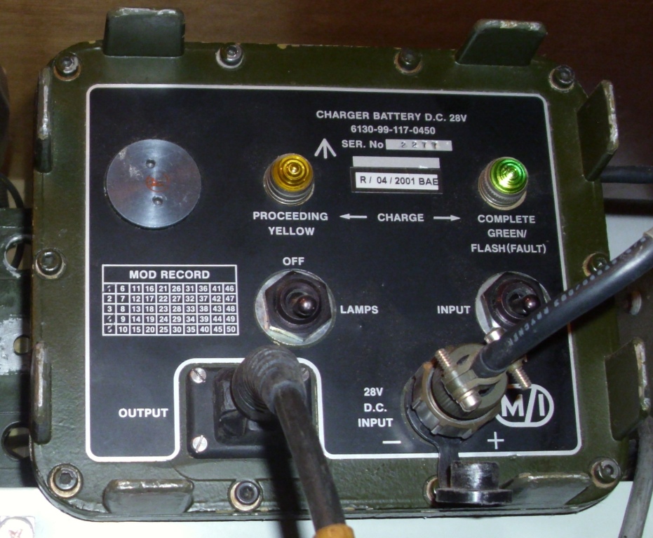
Figure1: Battery Charger
Exhausted Clansman batteries can be refurbished with new cells, and then charged on a standard Clansman charger. It is also possible to refurbish other batteries and use the Clansman charger to charge them. The article by Colin Guy G4DDI in the VMARS Newsletter 27 (February 2003) covers the refurbishing of old Clansman batteries. This article covers the refurbishing of other batteries.
CLANSMAN CHARGER
The Clansman Charger comes in 2 types, a 12 volt and a 24 volt input unit.
It is designed to charge a 28 volt NiCd battery, and to sense the battery temperature,
so the charge can be terminated. When the battery reaches the fully charged state,
any further energy is converted to heat. The 4 pin output connector uses 2 pins
to supply the charging voltage, and 2 pins as temperature sensors,
to prevent overcharging. It will flash its GREEN light when there is no
battery attached. When connected to a battery with the 4 pin cable,
the GREEN light will then turn fully ON, and the YELLOW light will also turn ON,
to indicate that a charge is in progress. When the charge is completed,
the YELLOW light will turn OFF, but the GREEN light will remain ON.
This is for a normal Clansman 24 volt battery.
Figure1: Battery Charger
SENSOR
The sensor is merely a diode. It relies on the characteristics changing as
the temperature increases. Each battery has 2 sensors, one to measure the rise
in temperature of a cell that is being charged, and another to compare the ambient
temperature to. Each sensor is 2 diodes in series. They are connected to the
negative common, and normally have a 1.1 volt forward voltage drop.
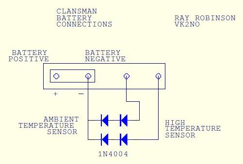
Figure2: Battery Connections.
BATTERIES
I had several non Clansman 24 volt batteries that needed refurbishing.
Two were RAVEN batteries made by Plessey and Saft, each different. Three were
PRC-F1 batteries, and all were different in some way. The RAVEN is a Plessey
designed and built radio, which includes an F-100 HF transceiver (PTR2331)
and an F-200 VHF transceiver (PTR4400U). Both use the same 24 volt battery
which comes in several varieties. There is a Primary battery (non re-chargeable)
BA-F300 of 8 AH capacity, and made by SAFT. There is a Secondary battery
(re-chargeable) made by Plessey PVU4264 of 4.5 AH. The PRC-F1 is an HF backpack
made by AWA for the Vietnam conflict. It used a BB-F1 24 volt rechargeable battery.
BATTERY ADAPTER
The 4 wire Clansman battery charging cable simply plugs directly into the
Clansman battery. I had a choice of fitting a 4 pin connector to each individual
battery, as in the Clansman batteries, but I chose to make one adapter for each
battery style. I used a metal tub from the junk box, and this luckily happened
to be the correct size for both batteries. For the PRC-F1 battery, I used 4 spring
terminals, the type that are used for aerial and earth connections on a valve radio.
These were mounted on some Perspex at the end of the tub, to push against the 4
contacts on the battery end. Two locating posts were added, so that the battery
could only be inserted the correct way. The spring terminals were wired to a
standard Clansman 4 pin battery connector.
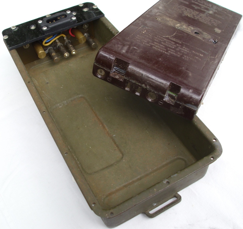
Figure3: PRC-F1 Charger Adapter
For the RAVEN battery, I used 2 spring terminals to push against the sensor contacts. The battery contacts were a spring type, so only 2 brass posts were needed. These were mounted on some bakelite. A metal plate was fitted to the top of the tub, and I cut holes for the 4 locating keys on the battery, 2 slots to engage the battery clamps, and the contact and sensor holes. The bakelite carrying the battery posts and spring terminals was screwed to the plate. The spring terminals and posts were wired to a standard Clansman 4 pin battery connector.
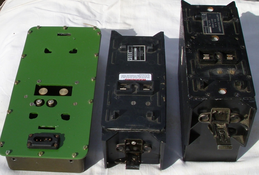
Figure4: RAVEN Charger Adapter and 2 batteries
PRC-F1 BATTERY
Each battery had 2 terminals on one end, marked positive and negative.
One battery had an extra 2 small terminals, which were probably for charge sensing,
but this battery was acquired already emptied, so no sensors were in place and
their type was unknown. The other 2 battery packs were opened and the old cells
removed. There were 22 of them in a series arrangement. They were a 4/5 Sub C size
NiCd type. The 2 battery cases that did not have the extra terminals, were drilled
and 2 countersunk brass screws were added on the end, in the same position that
the other 2 contacts were located.

Figure5: Old PRC-F1 Battery
Some new NiMH type cells of 1.6 AH capacity were purchased, which had tabs attached. To sense the cell temperature, I placed a diode against a cell, and held it in place with heat shrink tubing. I did this to 2 cells.
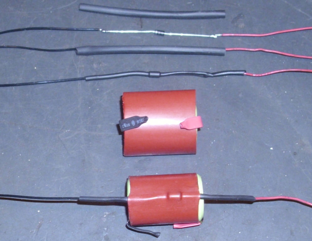
Figure 6: Cell and Sensor
All the cells were placed in the battery pack and connected in series, and connected to the positive and negative terminals. The two cells with the two sensors were positioned in the middle. These 2 diodes were connected in series and attached to the negative terminal, and to the battery sensor terminal. Two other diodes, for ambient temperature sensing, were placed in the battery pack, but well away from any cells. These 2 diodes were also connected in series and attached to the negative terminal, and to the ambient sensor terminal. The battery cover was glued on with silicon glue.
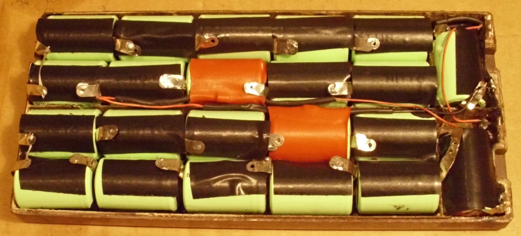
Figure 7: New PRC-F1 Battery
The PRC-F1 battery uses 22 cells, which will produce 30.5 volts when fully charged. The Clansman charger behaves slightly differently under these conditions. The charge cycle and temperature sensing operate normally, but both the GREEN light and YELLOW light will turn OFF, when the charge is completed.
RAVEN BATTERY
I had a primary and secondary battery that needed refurbishing. I removed
the old cells from each battery and purchased new cells. The larger battery case
had enough space for 20 batteries of the standard C size, in 9AH capacity.
The smaller battery case had enough space for 20 batteries of the Sub C size,
in 2.9AH capacity.
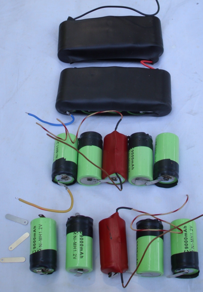
Figure 8: Battery Insides
The rechargeable RAVEN battery had no temperature sensors, so I added them. I added 2 countersunk screws near the battery terminals. To sense the cell temperature, I placed a diode against a cell, and held it in place with heat shrink tubing, in same manner as before. I did this to 2 cells. All the cells were placed in the pack and connected in series, and connected to the positive and negative terminals. The two cells with the two sensors were positioned in the middle. These 2 diodes were connected in series and attached to the negative terminal, and to the battery sensor terminal. Two other diodes, for ambient temperature sensing, were placed in the battery pack, but well away from any cells. These 2 diodes were also connected in series and attached to the negative terminal, and to the ambient sensor terminal. The battery cover was glued on with silicon glue. The larger RAVEN battery uses 20 cells, which will produce 27.7 volts when fully charged. The Clansman charger charges these normally. In the smaller RAVEN battery I fitted 21 cells, which will produce 29.1 volts when fully charged. The Clansman charger also charges these normally.
SUPPLIES
I purchased some cells and some battery tabs from the on line auction web site,
and also chose vendors that offered free postage. I chose NiMH rather than
NiCd cells, as they are a similar price, they have no memory effect, they
have the same cell voltage, the same charge and discharge characteristics, and
they weigh less. I chose the sizes that suited the battery cases. The standard C
size was $2.46 (1.99ukp), The Sub C size was $1.66 (1.27ukp), and the 4/5 Sub C
size was $1.97 (1.5ukp). These are more modern cells so they have a larger capacity
than the original cells, thus the batteries will last longer. The tabs were $5.37
(3.44 ukp) for a quantity of 100.
WELDER
The Sub C and 4/5 Sub C cells were available with attached tabs, so it was easy
to solder them together. The standard C cells did not have tabs, and I did not wish
to solder directly to the cells. They needed tabs attached, so I built a welder to
do the job. I copied my previous design, that was used to weld thermocouple wires to
gether, and I increased the power. The regulator was the same, but the main change
was to use three 50,000 uF capacitors instead of the three 4,700uF capacitors. These
were large old style computer capacitors, about the size of a can of soft drink.
I also used a larger SCR (110 Amp), about the physical size of a cotton reel. The
gate circuit is a little different, because in the previous model, if you held down
the pushbutton switch, it applied 20 volts continuously across the gate resistor and
gate, and overheated the resistor. This circuit uses a charged capacitor to fire the
gate circuit. I have also added a relay, so that foot switch can be used to trigger
the SCR. The capacitors and SCR are connected with copper bars, to bolts on the front
panel, and there are car battery sized cables to connect to the welder probes,
which are copper soldering iron tips. The electronics is just a 2 amp 18 volt
transformer, with a bridge rectifier, a smoothing capacitor, and an LM317 regulator.
The regulator can be adjusted between 5 volts and 25 volts using the front panel
potentiometer. There is a green LED to indicate that the power is ON. The relay
allows the regulator to charge the capacitors, which takes about 5 seconds.
There is a red LED to indicate the capacitors are charged. The transformer is
actually multi tapped, so the 18 volt tap is used to supply the regulator, and
the remainder of the winding, supplies 6 volts AC to the relay. The push button
switch energises the relay, or a foot switch can be connected to the plug on the
front panel. The mains input, fuse and switch is on the rear panel.
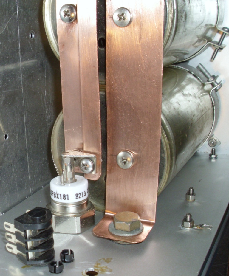
Figure 9: Capacitor and SCR
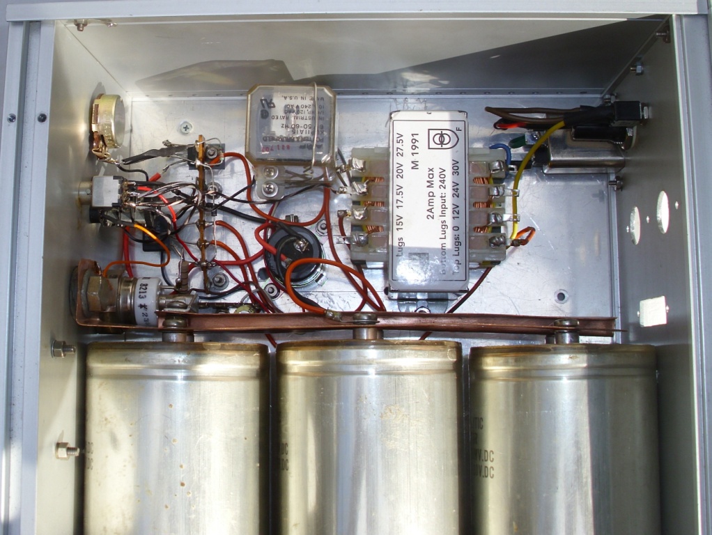
Figure 10: Internal View
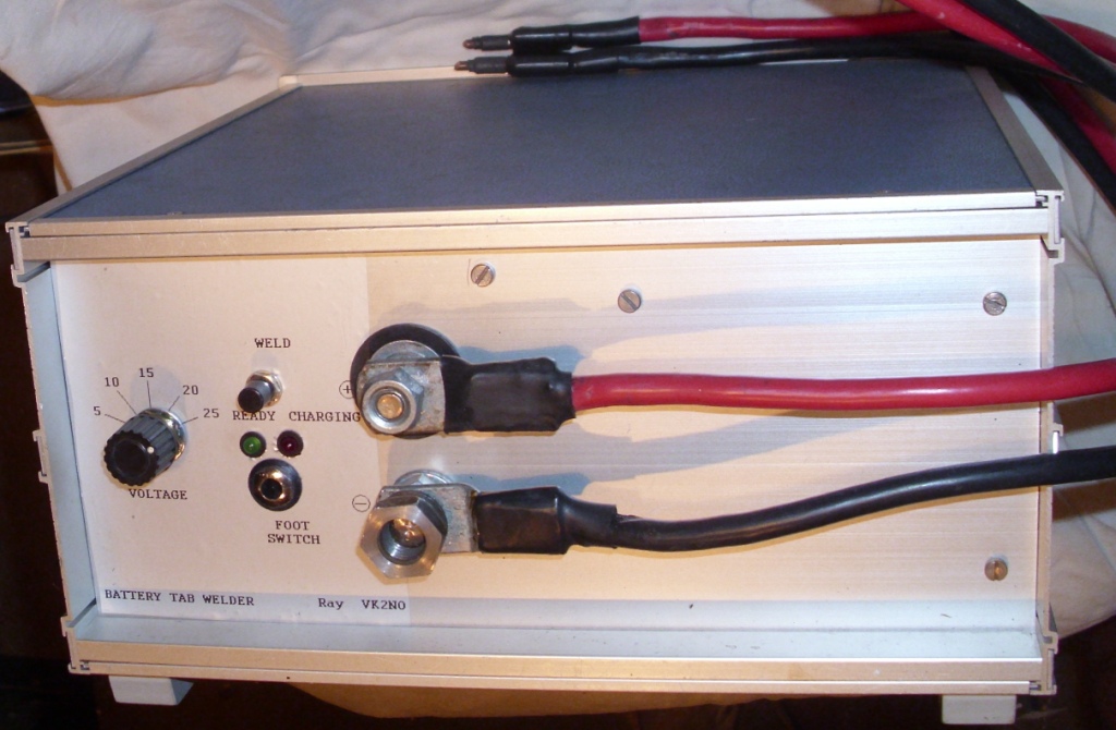
Figure 11: Front panel
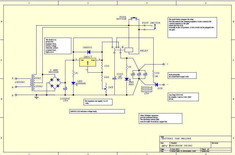
Figure 12: Welder
WELDS
The welding action occurs when the metal melts under high current conditions.
This is known as spot welding or resistance welding, because the melting occurs
in a small localised area (small spot) and the melting is due to heat buildup in
an area of high resistance. It is important to have the copper electrodes with a
point, and in good contact with the metals to be welded. In this case one electrode
is connected to the battery, and the other electrode is connected to the tab.
The area of high resistance (where the power will be dissipated) is therefore
where the two metals are in contact. Both the metals will melt and join together.
I hold the battery in a clamp, and apply the 2 electrodes, about 5mm apart, one
on the battery and one holding the tab on, apply physical pressure, and trigger
the welder. I usually do 4 or more welds per tab. The welder takes about 5 seconds
to recharge.
When a good weld occurs, there is a small audible click, and a small spark comes
out the side of the weld. Remove the electrodes, examine the area, and give the tab
a small tug. It should not come off, but if you pull hard, you can tear the metal,
and the tab will come off. Even electrode pressure should be applied to ensure good
contact is made. If not, a poor weld can occur. When this happens, the power is
dissipated, not in the desired area, but between one of the electrodes and the tab
(or battery). This usually results in a load audible bang, the metal is vapourised,
there is soot and small metal particles, and there is a 2 mm hole in the tab
(or battery). The area has to be cleaned, and the electrode filed to a point,
as the electrode end is usually blunted and plated with the tab metal. A small
amount of practice is required, until your technique is perfected. Practice on
an old battery and a tab.
Copyright 2017
Ray Robinson VK2NO